
Motor Housing Cooling Channel Design: 12.5 kW PM Motor CFD Case
An anonymized design-review case: a four-branch Ø5 mm housing cooling channel for a 12.5 kW permanent-magnet motor, with loss inputs, CFD setup, 13 kPa pressure loss, and why an air-gap model update moved the predicted magnet peak by about 78 K.
Working on a copper part? Start a project review — share a brief; CAD can follow.
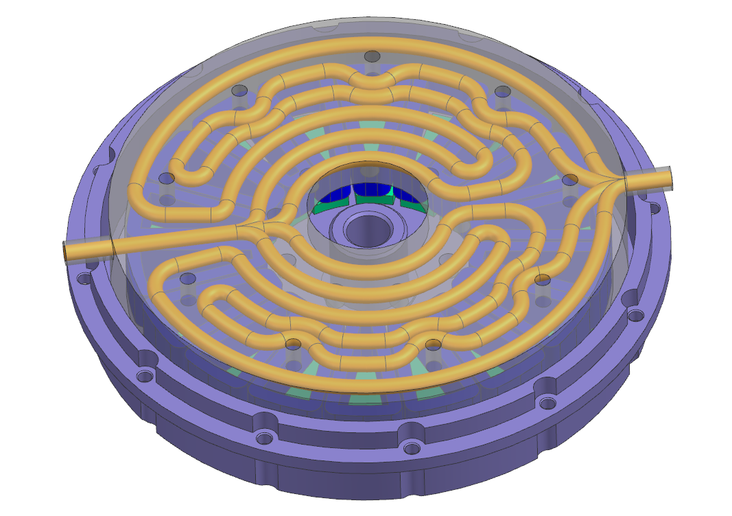
This is an anonymized design-review case from our thermal engineering work, published with the customer’s permission. A four-branch, Ø5 mm water channel in the motor housing kept the stator and winding within a moderate range at the 12.5 kW operating point. The same study showed that the rotor and magnet temperatures were governed by how the air gap was modeled, not by the housing channel. That finding changed the next design decision.
Project brief
The customer needed a liquid-cooled housing for a permanent-magnet motor. The channel had to fit around existing assembly features, and the design team wanted to know two things before committing to a manufacturing route:
- Can a housing channel at a modest flow rate hold the stator and winding at an acceptable temperature?
- Which part of the motor sets the thermal limit once the housing is cooled?
The operating point and loss split came from the customer’s electromagnetic analysis.
| Item | Value |
|---|---|
| Operating point | 12.5 kW at 5000 rpm (125 A) |
| Stator core loss | 143.9 W (loss density 860,699.8 W/m³) |
| Winding loss | 420.6 W (loss density 10,428,031.6 W/m³) |
| Rotor core loss | 52.39 W (loss density 508,221.5 W/m³) |
| Magnet loss | 38.9 W (loss density 659,173.1 W/m³) |
| Total loss | 655.8 W (sum of the four components above) |
The winding carries about 64% of the total loss, which is why most cooling concepts start at the stator side. The rest of this case shows why that is not the whole story.
Channel concept
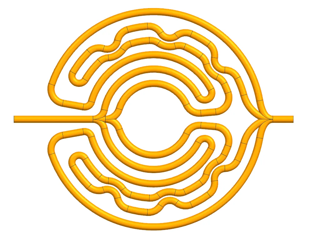
- Section: Ø5 mm round channel.
- Topology: one inlet splits into four branches, which rejoin at one outlet. Splitting the flow keeps each branch short and limits pressure loss compared with one long serpentine.
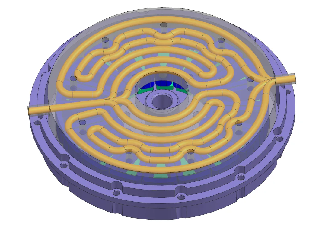
- Routing: the branches weave around bolt holes and other assembly features in the housing instead of running in a straight drilled pattern.
That routing is the reason the concept was reviewed for additive manufacturing. Curved branches that avoid fasteners are difficult to produce by drilling and plugging, and a cast core adds tooling and core-removal risk. A printed housing or insert can follow the path directly, provided the channel can be cleaned, inspected, and pressure tested. See conformal cooling inserts and internal-channel cleaning for those checks.
CFD setup
| Setting | Value used |
|---|---|
| Solver mode | Steady state (first screening pass, chosen to limit computation time) |
| Coolant | Water |
| Inlet | 5 L/min at 26.85 °C (300 K) |
| Motor materials | Aluminum, copper, stainless steel, with properties from the solver library |
| Magnet material | NdFeB: thermal conductivity 9 W/(m·K), density 7.5 g/cm³, specific heat 0.5 kJ/(kg·K) |
| Heat sources | Volumetric losses per component from the table above |
| Rotor-side cooling | None in this iteration |
Hand check on the coolant. At 5 L/min (about 0.083 kg/s) and a specific heat of about 4.18 kJ/(kg·K), removing the full 655.8 W raises the water temperature by roughly 1.9 K. This is our own energy-balance estimate, not a solver output. A small coolant rise means the housing-side limit is the conduction path from the heat sources to the channel wall, not the coolant capacity.
Pressure loss. The model predicted 13 kPa across the four-branch channel at 5 L/min. This value was the same in both iterations below because the channel geometry did not change.
Results: baseline model versus updated air-gap model
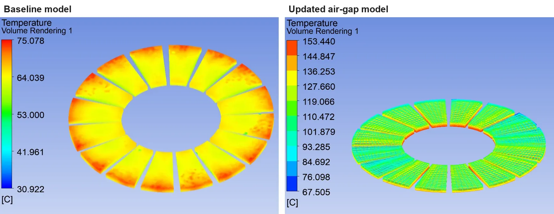
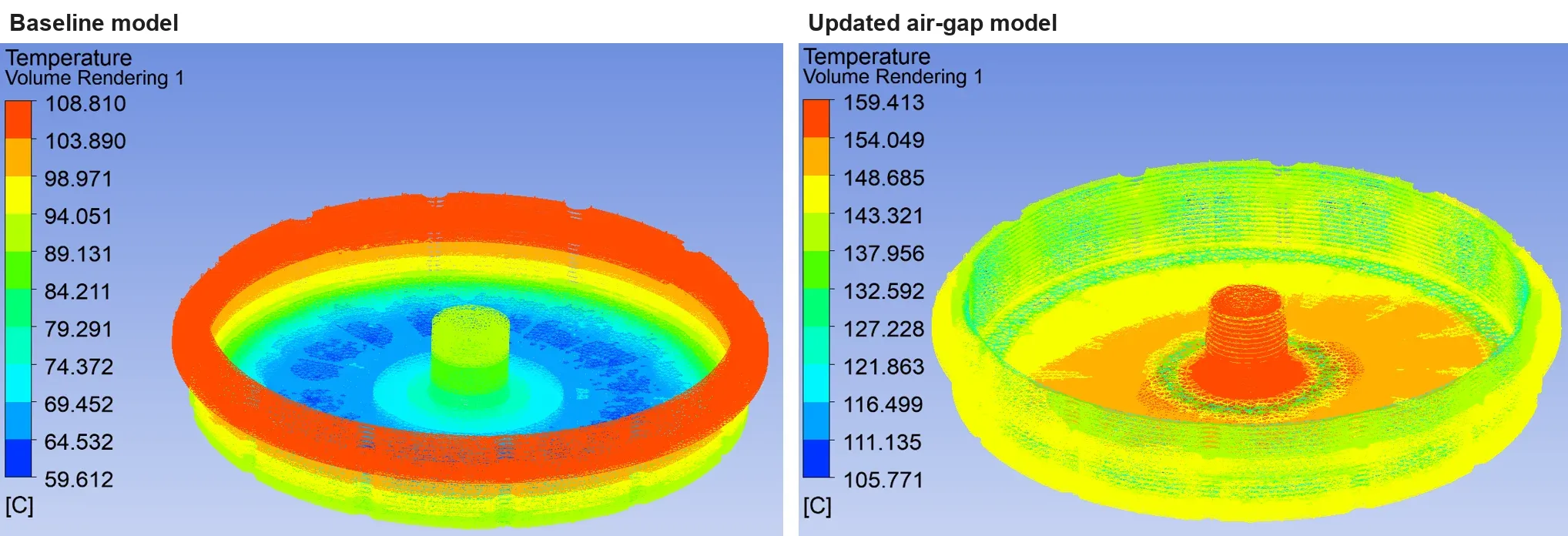
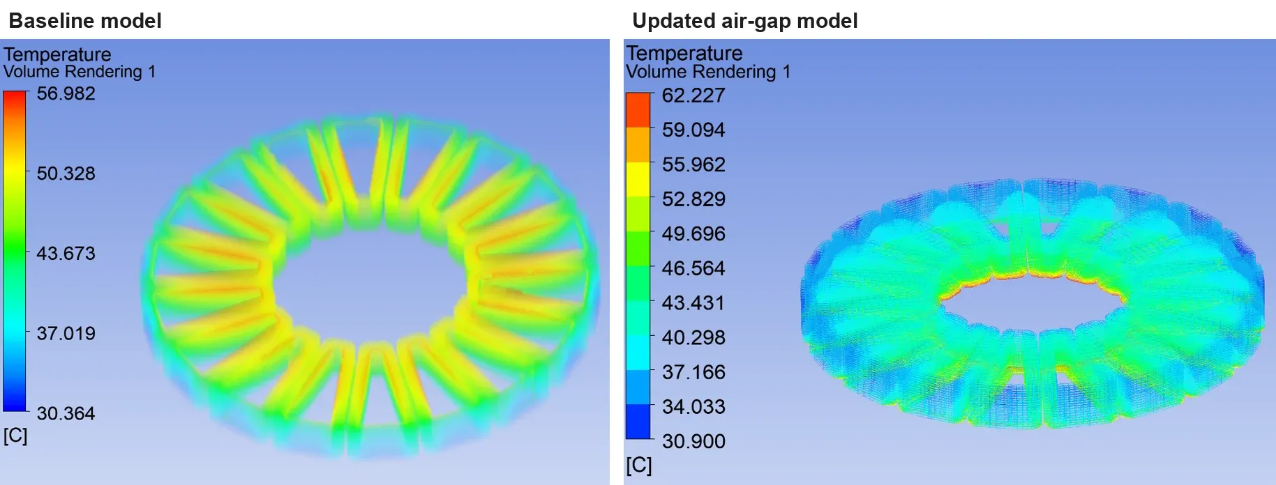
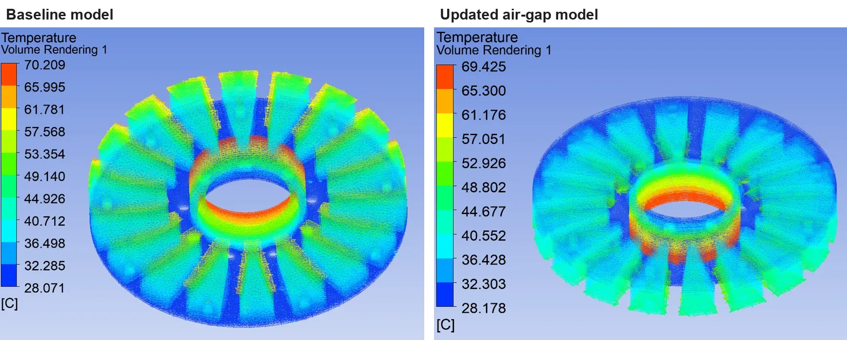
The team ran the model twice. The second run changed only the air-gap representation between stator and rotor. The table lists the temperature range shown in each component’s result plot.
| Component | Baseline model | Updated air-gap model | Change in peak |
|---|---|---|---|
| Magnets | 30.9–75.1 °C | 67.5–153.4 °C | +78.3 K |
| Rotor core | 59.6–108.8 °C | 105.8–159.4 °C | +50.6 K |
| Winding | 30.4–57.0 °C | 30.9–62.2 °C | +5.2 K |
| Stator core | 28.1–70.2 °C | 28.2–69.4 °C | −0.8 K |
Each image pair below uses the solver’s own color scale for each run. Read the legend values, not the colors, when comparing.
What the results mean
The housing channel did its job on the stator side. The stator core and winding results barely moved between runs. Their heat reaches the housing wall through solid conduction, and the four-branch channel removes it.
The rotor side is limited by the air gap, not by the housing. The rotor and magnets have no cooling of their own in this design. Their heat must cross the air gap to the stator, or leave through the shaft and bearings. When the air-gap model was updated, the predicted magnet peak rose by about 78 K while the stator side stayed almost unchanged. That makes the air-gap heat-transfer assumption the dominant uncertainty in the whole study.
More housing cooling would not fix it. Adding flow or channel area to the housing would mostly cool parts that are already within range. The decision moved to the rotor-side path instead.
Decisions this study set up
The review produced a list of open decisions rather than a frozen design:
- Validate the air-gap heat transfer. Use a correlation suited to the rotating gap and the actual clearance, or measured data from a comparable motor, before trusting either run.
- Check the magnet grade limit. Compare the predicted magnet peak with the maximum operating temperature of the specified magnet grade. If the margin is small, rotor-side cooling becomes a requirement, not an option.
- Evaluate rotor-side cooling. Shaft cooling, end-region airflow, or a different rotor heat path should be compared on the same model.
- Add transient duty cases. Steady state was a screening choice. Peak-power duty and thermal time constants decide whether a short overload is acceptable.
- Only then freeze the housing channel and move to manufacturing review: wall thickness around the branches, powder removal from each branch, pressure test, and flow balance between the four branches.
This order matters for cost. Printing a housing before the rotor-side question is settled risks paying for hardware that solves the wrong limit.
What this case shows about our thermal design work
- We start from the customer’s loss map and operating point, not from a generic heat load.
- We state every boundary condition and simplification, so a result can be challenged.
- We check results with simple energy balances alongside the CFD.
- We report when a model assumption, not the hardware, controls the answer, and we change the next decision accordingly.
The same workflow applies to copper cold plates, heat exchangers, and other cooled hardware. The full method is described on the thermal design and validation page.
Start a similar review
Send what you have through the secure RFQ form: the loss map or heat load by component, operating point and duty cycle, coolant and allowable flow and pressure loss, the envelope and assembly features the channel must avoid, and the temperature limits that matter, such as winding insulation class or magnet grade. CAD can follow. We reply within 2 business days and can sign your NDA before you share files.
Copper AM quotation
Is copper AM a fit for your part?
Describe the part, its job, and the question holding up your decision. Add quantity and critical requirements if known; CAD can follow.
NDA available on request. We reply within 2 business days.
Before you submit: Copper AM capabilities and review scope.
