
Copper heat sinks
Custom copper heat sinks, from CAD review to 3D printing
For OEM and engineering teams developing complex fins, pins, integrated cooling paths, or constrained thermal hardware. Send CAD or a thermal brief; we will compare LPBF copper AM with machining, skiving, and brazing before quoting.

When copper AM creates value in a custom heat sink
Printed copper is useful when the geometry solves a real thermal or packaging constraint. It is not automatically better than CNC, skiving, or brazed copper construction.
Fins, pins, channels, or hybrid structures can be reviewed when airflow, pressure drop, and cleaning access are realistic.
Internal liquid passages or combined heat sink and manifold features can be useful when leak and inspection requirements are clear.
Copper AM may help when thermal surfaces, mounting features, and routing need to fit into a compact envelope.
Choose the heat sink route before quotation
The strongest RFQs separate the heat sink function from the manufacturing route. This avoids forcing LPBF onto a part that should be machined, skived, brazed, or converted into a cold plate.
Often better for flat bases, simple fins, drilled holes, rectangular envelopes, and fabricated copper heat sinks where the main value is machining accuracy.
Worth reviewing for dense pins, curved airflow paths, integrated manifolds, internal passages, unusual mounting, or low-volume thermal hardware.
When airflow cannot meet the thermal target, the right answer may be a liquid cold plate rather than a more aggressive copper heatsink.
Define what the heat sink order must prove
A drawing-compliant component and a demonstrated system temperature are different deliverables. Separate manufacturing scope from thermal development before comparing quotations.
Send the controlled CAD, drawing revision, finished material state, prototype or batch quantity, and inspection requirements. The quote should identify machining, finishing and included records. Meeting the drawing does not by itself demonstrate the temperature of the customer assembly.
Send the temperature gap, heat-source footprint, installed fan or coolant conditions, envelope and interfaces. Include baseline test data if available; a sketch can start a scoped review. Agree design work, prototype supply, test ownership and the release decision separately.
What to send for a custom copper heat sink quote
A simple custom copper heatsink drawing can support a basic quotation. Complex thermal parts need enough boundary conditions to avoid quoting a geometry that cannot be accepted later.
Geometry and mounting
Send CAD and drawings for base thickness, fin field, mounting holes, datum faces, contact areas, channels, and machining stock.
Thermal boundary conditions
Include heat load, target temperature, airflow or coolant, interface material, clamp approach, and available test method if known.
Quantity and acceptance
State prototype or batch quantity, material preference, flatness, surface finish, inspection, and thermal validation requirements.
Decision points before quotation
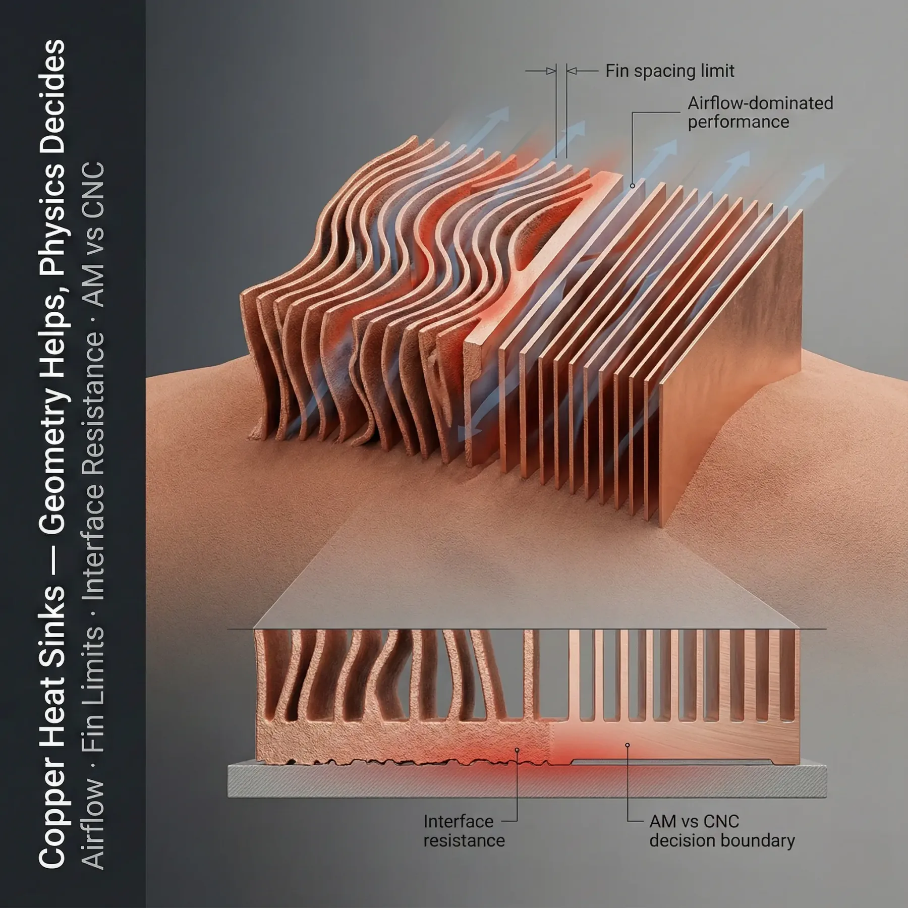
Most heat sink surprises come from interface, air-side, coolant-side, or post-processing requirements rather than copper conductivity alone.
Minimum fin thickness, spacing, aspect ratio, support strategy, powder removal, and cleaning access affect feasibility.
Contact flatness, surface finish, clamp load, TIM choice, and machining plan often dominate final thermal resistance.
Pure copper, CuCrZr, or GRCop-42 should be reviewed against conductivity, strength, temperature, and heat treatment needs.
Share inlet temperature, the fan curve or coolant flow, and the pressure budget. Review the installed flow path and bypass gaps: a free-air fan rating does not establish the flow through dense fins.
Machining, polishing, heat treatment, cleaning, coating, and plating requirements should be known before quoting.
Agree the heat input, assembly orientation, clamp and interface conditions, sensor locations, and temperature limits. Compare designs at the same operating point, then confirm the selected route in the intended assembly.
Replacing an underperforming copper heat sink?
Start with the failed requirement and an assembly view, not a request for more fins. These observations help define the review; none is a diagnosis without the operating data.
Map the sensor locations and the package-to-base heat path. Include TIM, contact area, clamp method and flatness. An interface or package bottleneck needs review before changing the external fin field.
Show inlet air temperature, fan control, ducting, nearby obstructions and bypass gaps in both setups. Compare the installed flow path; the same fan model does not establish the same flow through two different heat sinks.
Provide both model revisions and the conditions used for the baseline. Separate predicted improvement from measured performance, then agree the evidence needed before buying a production batch.
Related engineering guides
Use these before adding unnecessary requirements to a custom copper heat sink RFQ.
Use this before committing to LPBF when fins, pins, internal channels, airflow, finishing, and cost need a go or no-go decision.
Use this when the design has thin fins, dense channels, powder removal risk, or inspection limits.
Compare conductivity, strength, softening behavior, heat treatment, interfaces, and finished-component evidence.
Custom copper heat sink RFQ questions
Use these checks before requesting pricing for a copper heatsink, 3D printed copper heat sink, or liquid-cooled thermal part.
Can you quote a custom copper heatsink from a CAD file?
Yes, if the CAD and drawing define the geometry, quantity, interface surfaces, mounting method, and thermal target. For a serious quote, include heat load, airflow or coolant conditions, flatness, surface finish, and validation requirements.
When is a 3D printed copper heat sink better than CNC machining?
LPBF copper AM is most useful when the heat sink needs complex airflow paths, internal channels, integrated mounting, dense features, or geometry that would require many machined or brazed pieces.
When should fabricated copper heat sinks stay conventional?
Fabricated copper heat sinks are often the better route for simple plates, straight fins, drilled holes, skived geometries, or brazed assemblies where the main value is cost, flatness, or straightforward machining rather than hidden internal geometry.
When should a copper heat sink become a copper cold plate?
If airflow, fan power, noise, or available volume cannot meet the thermal target, a liquid cold plate may be the better copper thermal hardware route. The RFQ should compare thermal resistance and pressure drop, not only material conductivity.
What causes custom copper heat sinks to miss performance?
Common causes are weak thermal boundary conditions, poor contact flatness, excessive TIM thickness, fin spacing that starves airflow, blocked internal channels, and acceptance tests that do not match the final assembly.
What if the thermal design is not ready for quotation?
Start with the heat load, source footprint, maximum component temperature, inlet air or coolant temperature, available space, and mounting constraints. Share the fan curve or coolant flow and pressure budget if known. Mark missing values as open so the review can separate assumptions from confirmed requirements before committing to a fin or channel layout.
Can you review a replacement for an underperforming heat sink?
Yes. Share the existing geometry, an assembly view, measured temperatures with sensor locations, heat load, fan settings or coolant conditions, and the limit being missed. Identify what must remain unchanged. The first decision is whether the gap needs a different heat sink, an interface or flow-path change, or a revised system requirement; a more complex printed part is not automatically the answer.
Send drawings, quantity, and copper heat sink requirements
Submit the CAD package and critical thermal requirements. We will compare machining, skiving, brazing, LPBF copper AM, and cold plate options before responding with a quotation or clarification questions.