
Pure Copper vs CuCrZr for 3D Printed Heat Transfer Parts
Compare pure copper and CuCrZr at the same thermal duty: isolate conductivity sensitivity, then review manufacturable geometry, interfaces, flow and release evidence.
Working on a copper part? Start a project review — share a brief; CAD can follow.

Pure copper and CuCrZr can both be candidates for a 3D printed heat transfer part. First isolate the benefit of conductivity in the same geometry. Then compare manufacturable designs at the same duty, including interfaces, coolant-loop limits and mechanical requirements. A material data sheet alone cannot select the better finished component.
Illustration note: the existing cover and figures are AI-generated concepts, not photographs of delivered parts, measured comparisons or completed tests. They are not evidence of finished-part performance.
A cold plate, heat exchanger or heat spreader is rarely just a block of conductive metal. It also has interfaces, mounting loads, surfaces, ports and possibly a pressure boundary. This article addresses a specific decision: does a change from a documented CuCrZr route to a documented pure-copper route deliver a useful thermal benefit without making the finished part unacceptable?
For the broader choice of material designations and supplier data, use the copper alloy selection guide. For the project-wide analysis and evidence plan, use thermal design and validation.
First Gate: Where Is the Temperature Rise Coming From?
Before comparing alloys, agree what temperature must be limited and under which duty. “Lower temperature” can mean a lower peak device temperature, a more uniform contact face, a lower outlet temperature or a transient limit. Those are different objectives.
Trace the heat path:
- Heat source and its spatial distribution, not only total power.
- Contact interface, mounting condition and thermal interface material.
- Conduction and spreading through the finished copper body.
- Heat transfer into the coolant or surrounding air.
- Fluid temperature rise, flow distribution and the rest of the cooling loop.
If the dominant resistance is outside the bulk metal, improving the metal’s conductivity may produce only a small system benefit. Conversely, if conduction through the body is a large part of the resistance, conductivity deserves closer attention. Establish that sensitivity before paying for a route change.
A Transparent Conductivity-Sensitivity Example
For a simple steady, one-dimensional slab with constant properties, bulk conduction resistance is R_bulk = L / (k × A), where L is path length, k is thermal conductivity and A is area. Series resistances add; MIT’s conduction notes explain that model.
The following is an original, deliberately simplified calculation—not Cu/CuCrZr material data, a customer result or a prediction for an actual cold plate.
Assume:
- Geometry, heat load, interfaces and cooling conditions are unchanged.
- Total resistance is represented by R_total = R_other + R_bulk.
- f is the original bulk-metal share of total resistance.
- The candidate material has 1.25 times the original conductivity; this ratio is hypothetical.
With the other resistance unchanged, new total resistance / old total resistance = (1 − f) + f / 1.25.
| Original bulk-metal share of total resistance | Hypothetical conductivity increase | Calculated total-resistance reduction |
|---|---|---|
| 10% | 25% | 2% |
| 50% | 25% | 10% |
| 90% | 25% | 18% |
The lesson is about sensitivity: the same material improvement can have very different value depending on where resistance sits.
This lumped model does not resolve three-dimensional spreading, local hot spots, changing fluid temperatures, flow maldistribution, temperature-dependent properties or transient operation. It is a screening calculation. Use an appropriate thermal model and agreed test conditions for a part-level decision, not these percentages as a performance claim.
To repeat the screening calculation, download the conductivity-sensitivity worksheet (CSV) and open it in a spreadsheet that evaluates formulas. Edit f (the original bulk-metal resistance share, from 0 to 1) and r (candidate conductivity divided by original conductivity, greater than 0). The calculation is new/old total resistance = (1 − f) + f/r; reduction is 1 − new/old. Results are fractions: 0.02 means 2%, and a negative reduction means resistance increased. If the importer displays formulas as text, use the equation above rather than treating the text as a result.
The three prefilled rows reproduce the hypothetical example, not measured alloy properties. Use documented conductivity values at the relevant material state and temperature for a project review, and do not guess f from a material data sheet. Establish it from a justified resistance model or sensitivity analysis. The worksheet keeps geometry and all other resistance unchanged; it cannot predict benefits from changing channels, contact interfaces or coolant flow.
Compare in Two Passes, Not One Mixed Simulation
Changing material, channel geometry and flow conditions in a single comparison makes it difficult to identify why a result changed. Separate the material question from the manufacturable-product question.
Pass 1: Same Geometry, Material Sensitivity
Keep the geometry and boundary conditions fixed. Change only the relevant documented material properties to establish whether conductivity has a meaningful influence on the defined thermal objective.
Use properties associated with the proposed material state and temperature range. If the values are uncertain, evaluate a justified range and label the result provisional. This pass does not prove that either geometry can be manufactured or accepted.
Pass 2: Manufacturable Designs, Same Duty
Now allow each candidate to use geometry that its manufacturing route can support, while holding the required function and interfaces comparable.
| Comparison item | Keep aligned or explicitly report | Misleading comparison to avoid |
|---|---|---|
| Thermal duty | Heat-source map, heat load, duty cycle and temperature metric | Different heater coverage or a different peak-temperature location |
| Envelope and interfaces | Available volume, contact area, mounting and interface material | A larger part or improved interface presented as a material-only gain |
| Coolant boundary | Fluid, inlet temperature and the chosen loop constraint | Colder inlet fluid on one candidate |
| Hydraulic basis | Fixed flow, available pressure or pump-power constraint; state which is controlled | Equal flow at unequal pressure drop presented as equal pumping effort |
| Geometry and surfaces | Manufacturable walls, channels, roughness assumptions and finishing scope | Ideal smooth channels compared with an as-built surface assumption |
| Material state | Documented properties for each proposed delivered route | As-built data for one alloy versus aged data for another without disclosure |
| Mechanical duty | Pressure differential, loads, service temperature and interfaces | Thermal compliance without checking the required structural or sealing function |
If both candidates are evaluated at the same flow but have different pressure losses, report those losses. That is an equal-flow comparison, not automatically an equal-pump comparison. For a pump-constrained loop, evaluate the attainable operating point with the loop and pump information; do not assume the same flow remains available.
For heat exchangers with two fluid streams, specify both sides and the temperature/performance metric. For an air-cooled heat sink, define the air-side flow or fan constraint rather than borrowing a liquid-loop assumption.
Pure Copper: When the Conductivity Benefit Is Worth Pursuing
Pure copper is worth reviewing when the bulk heat path materially limits the objective and the proposed finished state can meet the other requirements. Broad heat spreaders and supported thermal interfaces can be useful candidates, but geometry and loading—not the application label alone—determine suitability.
Check these practical limits:
- Can the thermal face meet its requirement after processing and under the specified mounting condition?
- Are threads, port bosses and thin sections adequate for their actual loads and temperatures?
- Does the design provide access for channel cleaning and verification?
- Is the relevant conductivity supported for the quoted manufacturing route?
- Does the material-only benefit remain useful once interface and cooling uncertainties are included?
The pure copper manufacturing guide addresses process feasibility. A conductivity preference should not bypass that review.
CuCrZr: When a Documented Material State Supports the Combined Duty
CuCrZr deserves review when the component must transfer heat while meeting mechanical requirements associated with ports, walls, mounting or service exposure. It is not automatically required whenever a part contains pressure or threads.
The EOS CuCrZr product documentation ties its combination of conductivity and mechanical properties to heat treatment. That supports asking for the delivered state, not assuming universal properties for all printed CuCrZr.
Confirm the property basis, process sequence and evidence relevant to the proposed part. Do not assemble a fictitious material state from the highest strength in one condition and highest conductivity in another. Electrical conductivity is also not a direct substitute for thermal conductivity without a justified correlation.
Use the CuCrZr heat-treatment guide for that process discussion, and the strength-led selection guide when mechanical constraints dominate.
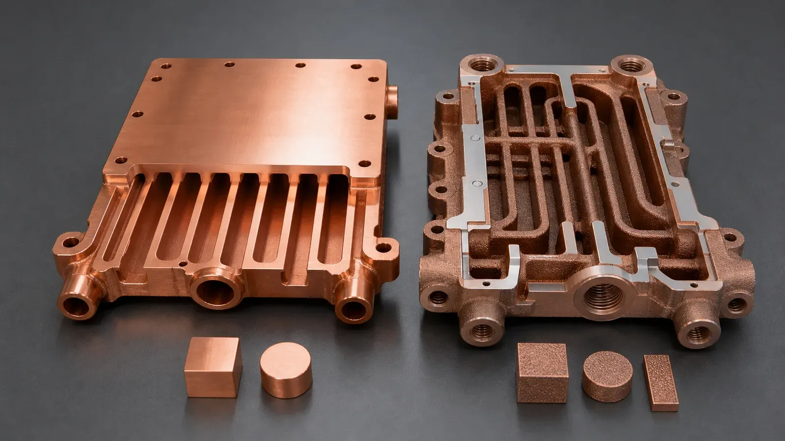
Geometry, walls, ports and surface assumptions must be disclosed alongside material properties. Two different pictured designs do not establish a thermal winner.
Example Decision Record: A Better Model Is Not Yet a Released Part
This is a hypothetical review scenario, not a reported project.
Suppose Pass 1 predicts a lower peak temperature for a pure-copper candidate. During Pass 2, one channel must be enlarged for cleaning access, a port region needs revised geometry, and the finished interface must be checked under the actual clamp load.
Do not carry the original material-only result directly into a performance promise:
- Update the manufacturable geometry and surface assumptions.
- Repeat the comparison at the same thermal and hydraulic duty.
- Check whether the predicted difference is meaningful relative to input and measurement uncertainty.
- Identify the remaining material-state, dimensional, pressure/leak and thermal evidence required for the application.
Possible outcomes include retaining pure copper, retaining CuCrZr, revising both candidates, or selecting a conventional route. If the benefit is smaller than the unresolved uncertainty, the next useful action is better evidence—not a stronger headline.
This is also a stopping rule for development spend: pause optimization when neither candidate has a credible manufacturing or acceptance route, and close that gap first.
Interfaces and Validation Can Change the Decision
Compare the finished interface as part of the thermal system. Specify flatness and roughness where functional, the mounting condition, the thermal interface material, and any required inspection after relevant processing or exposure. Avoid a universal flatness number disconnected from area, assembly and function.
A stronger material could support a more stable interface in a particular design, but that benefit must be demonstrated for the actual load and state. It is not an inherent system-performance guarantee.
Both candidate materials need the same applicable functional acceptance gates. Their supporting material/process evidence may differ:
| Evidence level | Question it can address | What it does not prove by itself |
|---|---|---|
| Material-state data or agreed witness testing | Are the specified properties supported for the delivered route? | Local geometry, cleaning or sealing of the actual part |
| Dimensional and surface inspection | Do the specified finished features meet the drawing and inspection condition? | Thermal duty under an untested mounting condition |
| Appropriate pressure/leak tests | Does the defined boundary meet the agreed test criterion? | Thermal performance or a different leak-test sensitivity |
| Flow and pressure-drop checks | Is hydraulic behavior acceptable under the test conditions? | Heat removal at the required thermal duty |
| Thermal test in the defined assembly | Does the agreed temperature/performance metric pass at that duty? | Other operating points or lifetime unless covered by the plan |
The scope should follow risk and agreed requirements. Not every development part needs every test. Do not replace a thermal test with a pressure hold, or interpret a coupon as finished-channel evidence.
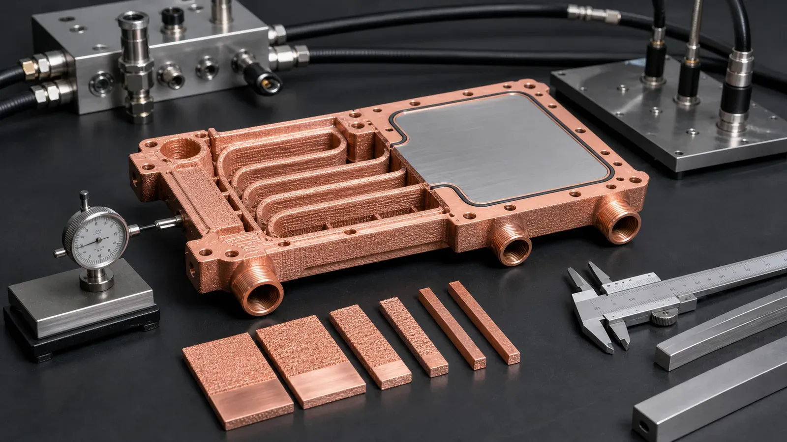
Illustrative only. A release record needs identified specimens or parts, methods, conditions, results and acceptance limits—not an equipment image.
Request a Useful Thermal Material Comparison
You do not need to settle the alloy before starting a review. Send the available geometry or sketch, the part’s function and the main known constraint, and mark the material as open to review.
To make the comparison actionable, add the following as they become available:
- Heat load and source footprint, temperature limit and steady/transient duty.
- Envelope, contact/interface details and mounting loads.
- Coolant and inlet temperature, plus the flow or pump/pressure constraint.
- Working pressure and any specified proof/leak boundary.
- Mandatory material designation, finished state or customer approval rules.
- Critical surfaces, cleaning expectations, quantity and development stage.
Use thermal design support when the boundary conditions or comparison method need development. For hardware quotation, start a thermal-part RFQ or email info@szcomo.com. Describe a cold plate, heat spreader or heat exchanger explicitly so that the review follows the actual component.
Once the material shortlist is settled, the material specification guide helps define the final state and acceptance evidence. Use the existing surface finish and tolerance guides for those drawing requirements.
FAQ
Is pure copper always better than CuCrZr for heat transfer?
No. Compare documented material properties first, then the finished designs at the same duty. The benefit depends on the share of resistance in the bulk metal, the interfaces, attainable flow and the geometry that can actually be manufactured and accepted.
Does a 25% conductivity increase mean a 25% cooler component?
No. In the simplified example above, a hypothetical 25% conductivity increase reduces total resistance by only 2% when the bulk metal initially accounts for 10% of that resistance. This is a mathematical illustration, not a copper-alloy property claim or a prediction for a real component.
Should pure copper and CuCrZr designs be compared at the same flow?
Only if fixed flow is the intended comparison basis. Report pressure drop as well. If the real loop is limited by available pressure or pumping power, compare attainable operation under that constraint; equal flow does not necessarily require equal pumping effort.
Does choosing CuCrZr remove the need to check pressure integrity?
No. Material properties do not establish the integrity of the printed wall, ports or seals. The actual boundary needs the applicable design review and agreed pressure/leak evidence, regardless of which alloy is selected.
Can we request a review before choosing the material?
Yes. Start with the available geometry, thermal duty and known constraints, leaving unknowns explicit. The useful first result is a conditional shortlist and a plan to close the remaining questions, not an unsupported promise that one alloy will perform better.
Copper AM quotation
Turn a thermal requirement into a reviewable brief
Describe the heat source, cooling constraints, and decision you need to make. Share existing calculations, sketches, or CAD if available; detailed design and validation scope must be agreed separately.
NDA available on request. We reply within 2 business days.
Before you submit: Thermal design and validation support.
