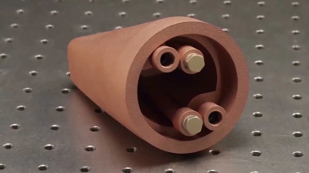
Engineering and DfAM
Review geometry, internal channels, material route, supports, powder removal, datums, and acceptance risk.
Copper additive manufacturing | Suzhou, China
We manufacture pure copper and copper-alloy parts from your CAD, with engineering support for DFM, thermal and flow analysis, and design iteration. Send CAD or a thermal brief for an engineering review and scoped quotation.
Prefer email?

Process
Green-laser LPBF
Materials
Pure Cu · CuCrZr
Output
Inspected parts
Service
Copper AM production
Scope
Print · machine · inspect
Start
CAD or thermal brief review
01 | Who we are
COPPER 3DP is the copper additive manufacturing service of Suzhou Como Precision Materials Co., Ltd. We review the drawing, manufacture the part, complete downstream operations, and supply the agreed inspection evidence.
The engineering discussion stays focused on the part: function, geometry, material state, downstream operations, acceptance evidence, quantity, and timing.
Send your drawingReview geometry, internal channels, material route, supports, powder removal, datums, and acceptance risk.
Produce commercially pure copper and copper alloy parts on a platform matched to the geometry.
Define heat treatment, support removal, CNC features, sealing faces, threads, polishing, or plating.
Agree dimensional, CT, pressure, leak, flow, conductivity, surface, and documentation requirements.
02 | What we make
We manufacture prototypes and production parts when internal channels, compact heat-transfer area, shaped current paths, or part consolidation make conventional fabrication inefficient.
Cold plates, compact heat exchangers, heat sinks, cooling blocks, and integrated manifolds.
Cooling plates, heat spreaders, compact manifolds, and hardware for power electronics.
Induction coils, busbars, electrodes, shaped current paths, and high-current components.
Waveguides, RF cavities, conductive structures, and vacuum-facing copper hardware.
Nozzles, injectors, manifolds, flow distributors, and parts with integral cooling passages.
Conformal-cooling inserts, thermal tooling, and copper-alloy structures for demanding environments.
03 | Thermal design support
A project can start with finished CAD or with heat load, temperature limits, coolant, flow or pressure-drop targets, available envelope, and interfaces. We turn those inputs into a scoped design, manufacturing, and validation route.
The selected geometry is project-specific. More surface area does not automatically mean better cooling once pressure drop, flow distribution, cleanability, and printability are considered.
Review the complete thermal design and validation workflow, or continue with the commercial paths for copper cold plates and copper heat exchangers.
Map heat sources, duty cycle, temperature limits, coolant, flow or pressure limits, envelope, and interfaces.
Assess channels, fins or microchannels, impingement, manifolds, and topology-led structures against the constraints.
Balance thermal response, uniformity, pressure drop, strength, powder removal, machining, and inspection access.
Define the agreed CAD and drawing scope, manufacturing route, prototype plan, and included simulation or test evidence.
Architecture, reconstruction, and evidence
Metal AM expands the available surface, fin, and channel design space. The value is realized only when the thermal concept can be simulated under defined conditions, rebuilt as manufacturable geometry, and tied to an agreed validation plan.
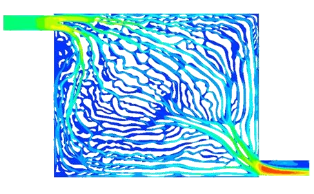
Reference study | flow field
A topology-led path is a concept, not a guarantee. Compare flow coverage, local velocity, and pressure loss under the agreed coolant and boundary conditions.
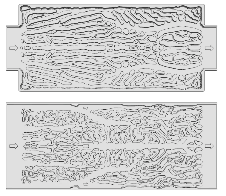
Reference study | model reconstruction
Convert optimization output into continuous passages with practical walls, powder exits, port transitions, machining stock, and inspection access.
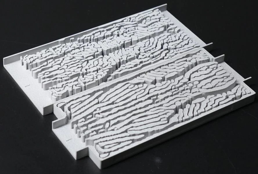
Reference study | physical print
Use the physical build to review feature continuity, channel access, edge conditions, cleaning or powder removal, and the dimensional, flow, leak, or thermal checks needed before the design is frozen.
Two valid starting points
Existing CAD moves into DfAM and production review. A thermal brief starts with concept development before the prototype route is agreed. Performance targets remain tied to agreed inputs and project-specific validation.
Useful design inputs
04 | Production capability
The drawing determines the material route, build class, orientation, supports, powder-removal strategy, and downstream operations. The quotation records the route selected for that part.
Laser route
532 nm green laser
Process route for reflective copper and copper alloy systems.
Build classes
5 envelope ranges
From compact development work to large-format production.
Largest build class
660 × 660 × 1300 mm
Final fit still depends on orientation, supports, and access.
Materials processed
Conductivity, strength, temperature, heat treatment, final state, and acceptance method are reviewed together. Feedstock selection is one input to the finished-part manufacturing route.
Check your material and part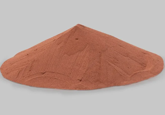
Selected when thermal or electrical conductivity is the primary design driver.
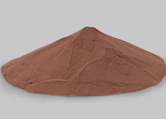
Selected when conductivity must be balanced with strength and thermal stability.
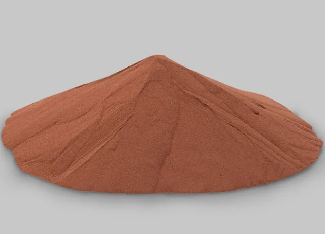
Assessed for application-specific copper alloy and elevated-temperature requirements.
Build capacity
The final build class is confirmed after part size, material, geometry, quantity, and current production requirements are reviewed.
05 | How we work
The process is locked around the agreed inputs, drawing, and acceptance criteria, so design, printing, post-processing, inspection, and quotation describe the same deliverable.
Send CAD or, for thermal-design work, the governing operating requirements, envelope, interfaces, quantity, and acceptance needs.
For scoped thermal-design projects, we develop and iterate cooling geometry before fixing the material, DfAM, finishing, and test route.
The part moves through green-laser LPBF, support removal, heat treatment, CNC, and specified finishing.
Inspection evidence is produced against the agreed scope before packaging and international delivery.
Engineering review
Add quantity, target timing, heat load or operating conditions, and the requirements that cannot be compromised.
06 | Parts and applications
These part forms show where copper LPBF is most useful: compact thermal structures, integrated flow features, shaped current paths, and geometries that remove joints or assembly steps.
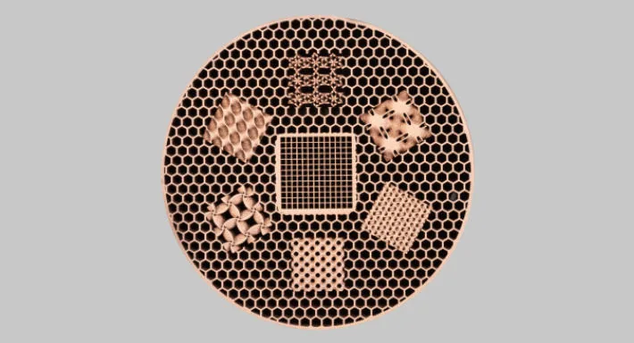
Dense surface area, compact flow paths, and monolithic thermal cores.
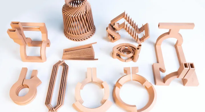
Integrated cooling, shaped current paths, and repeatable coil geometry.
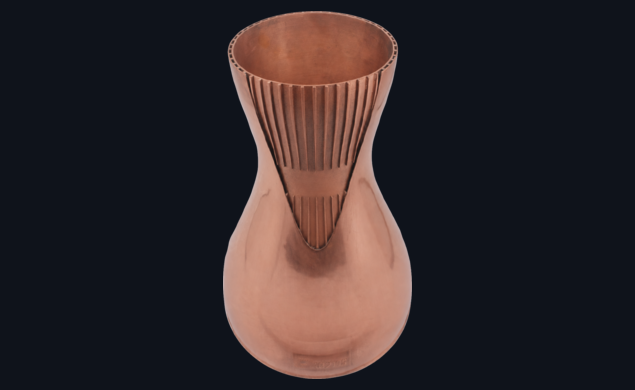
Internal passages, consolidated bodies, and heat-flux-focused geometry.
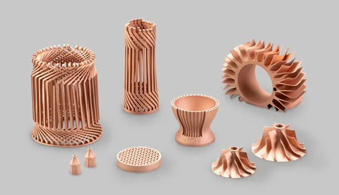
Geometry that combines thermal, structural, and fluid functions in fewer pieces.
07 | Start a project
Submit what is already known. If CAD is not yet available, provide the heat load, temperature target, coolant, flow or pressure limits, available envelope, and interfaces. Quantity, material preference, inspection, and target timing help us return a clear scope.
What you get back
We confirm whether LPBF is the right route for the part, and say so when CNC, skiving, or brazed copper is the better choice.
Wall, channel, fin, support, powder-removal, machining-stock, and inspection-access issues are marked before pricing.
Material route, heat treatment, machining, finishing, inspection, and delivery scope, or focused questions if inputs are missing.
Secure RFQ submission
Tell us what the part needs to do. Start with your contact details and a short brief; CAD and additional project details are optional.
Prefer not to use the form?
RFQ submitted
A reference is shown below. Keep it for follow-up. We reply within 2 business days from info@szcomo.com.
Email option
Copy this into your own email if useful. Send the drawing and what you know; leave unknown fields blank.
Subject: Copper 3D printing RFQ - [part name]

Hello COPPER 3DP,

Please review the attached CAD/drawings for quotation.

Part/application:
Attached files:
Quantity:
Material preference, if known:
Target lead time:
Critical dimensions or surfaces:
Operating conditions:
Inspection or test requirements:
Post-processing expected:

Notes:

Best regards,