
Component heat sources and duty
Allocate losses by component, define source footprints or volumetric heat generation, and record separate temperature limits, duty cycles, and transient events.
Thermal engineering for copper AM
Check whether a copper cooling design meets temperature and flow requirements at defined operating conditions. Connect CFD assumptions, manufacturable channels, and measured acceptance evidence before committing to a build.
Start with a thermal brief or CAD for a cold plate, heat exchanger, heat sink, or manifold. Agree the heat load, coolant, pressure budget, interfaces, and validation scope.
01 | Define the problem
A credible cooling design begins with the system constraint. Missing flow, pressure, interface, or acceptance data can make a visually sophisticated model impossible to quote or validate.
Allocate losses by component, define source footprints or volumetric heat generation, and record separate temperature limits, duty cycles, and transient events.
State the coolant, inlet condition, target flow, available pump head, pressure-drop budget, and working or proof pressure.
Model air gaps, contact resistance, material states, thermal interfaces, keep-outs, seals, ports, mounting, and the path from each source to the coolant.
Agree which dimensional, CT, cleanliness, flow, pressure, leak, or thermal checks will decide whether the part is accepted.
Inputs are marked as confirmed, assumed, or sensitivity-controlled, with an owner for each open item. If component losses, contact conditions, coolant limits, or acceptance targets are unknown, the result is treated as architecture screening rather than a validated temperature prediction.
02 | Screen the architecture
The source material did not identify one universally best internal structure. It screened posts, channels, fins, impingement, periodic surfaces, and topology-led paths by comparing heat transfer, pressure loss, formation quality, and product-scale verification.
| Candidate architecture | Observation from the supplied studies | What can make it fail | Evidence needed for a decision |
|---|---|---|---|
| Pin or post fields | In the supplied screening work, the tested post layouts carried a lower hydraulic penalty but offered limited heat-transfer improvement. | Bypass flow, weak local mixing, and unresolved hotspots can remain even when total pressure loss looks acceptable. | Temperature distribution, branch flow, and pressure drop at the same operating point. |
| Continuous channels | The evaluated channel concepts produced comparatively uniform cooling, but the hydraulic cost could become the dominant constraint. | A thermally attractive route can exceed the pump-head budget or starve parallel branches. | Heat-source temperatures, flow distribution, total pressure loss, and branch-to-branch balance. |
| Thin fins and microchannels | Reducing fin scale increases available area and can move active geometry closer to the heat source. | Print repeatability, powder removal, blockage, cleaning, wall continuity, and inspection become harder as scale falls. | Manufacturing coupons, cleaning route, internal inspection, thermal result, and pressure drop. |
| Jet impingement | The supplied concept comparison found impingement useful for peak-temperature reduction and temperature uniformity. | Nozzle loss, return-flow congestion, erosion, clogging, and pump demand can erase the local thermal gain. | Local heat-flux response, nozzle flow balance, return-flow field, pressure loss, and contamination plan. |
| TPMS or periodic surface cores | Three surface families were screened through nine coupons, then eight product-scale core configurations were compared for formation, heat transfer, and flow resistance. | A family with stronger heat transfer can also carry the highest pressure penalty; rankings are geometry- and boundary-condition-specific. | Coupon build evidence, internal inspection, paired thermal and pressure data, then product-scale confirmation. |
| Topology-led flow paths | Optimization can distribute flow or material beyond straight-fin layouts, but the raw result is only a design candidate. | Disconnected walls, abrupt transitions, trapped powder, inaccessible features, and uninspectable passages. | Reconstructed CAD, DfAM review, flow re-check, representative build, and agreed inspection access. |
These are project-specific screening observations from the supplied engineering material, not universal rankings. Geometry, material, scale, heat flux, coolant, flow range, and acceptance limits can change the outcome.
03 | Control model fidelity
A representative motor-cooling brief allocated losses to the winding, stator core, rotor core, and magnets, then routed one inlet into four parallel cooling branches around assembly keep-outs.
When a later model version updated the assembly air-gap representation, predicted component temperatures shifted materially and unevenly even though the channel concept and reported hydraulic loss remained similar. The lesson is not a performance number: the assembled heat path can matter more than another round of channel-shape refinement.
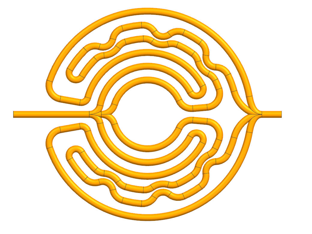
Model input | flow circuit
Record total flow, pump-head budget, branch resistance, local restrictions, and the distribution evidence needed before accepting a parallel circuit.
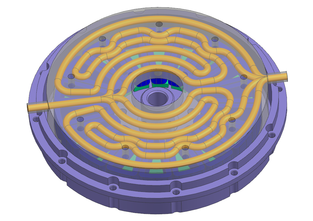
Model input | assembled heat path
Channel clearance, axial position, gaps, contacts, material interfaces, and source-to-coolant distance all belong in the model, not only in the final CAD review.
Separate winding, core, magnet, semiconductor, or other source losses and their temperature limits.
Record air gaps, interfaces, contact resistance, housings, fasteners, and the cooled surface location.
State property sources, mesh or discretization checks, convergence criteria, and energy balance.
Use steady state for screening where appropriate; add transient or sensitivity cases when duty or uncertainty requires them.
Source note: the two images above were extracted from the motor-cooling design brief supplied for this website. Project-specific dimensions, loads, temperatures, and operating values are intentionally omitted. The brief documents a steady-state model iteration, not a completed physical validation or manufacturing claim.
04 | Close the engineering loop
Simulation is one decision tool inside a larger workflow. The model, printable geometry, post-processing route, and validation plan must describe the same part and operating case.
Translate the operating problem into thermal, hydraulic, mechanical, interface, and acceptance constraints.
Compare conventional and additive architectures before committing to a complex internal geometry.
Evaluate candidates with traceable losses, properties, contacts, gaps, convergence checks, energy balance, and sensitivity review.
Turn promising results into continuous walls, transitions, powder exits, machining stock, and inspectable features.
Build the evidence plan around dimensional, flow, pressure, leak, cleanliness, and thermal requirements.
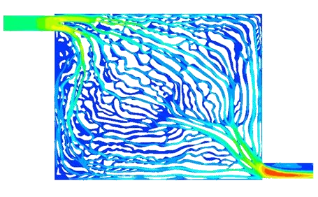
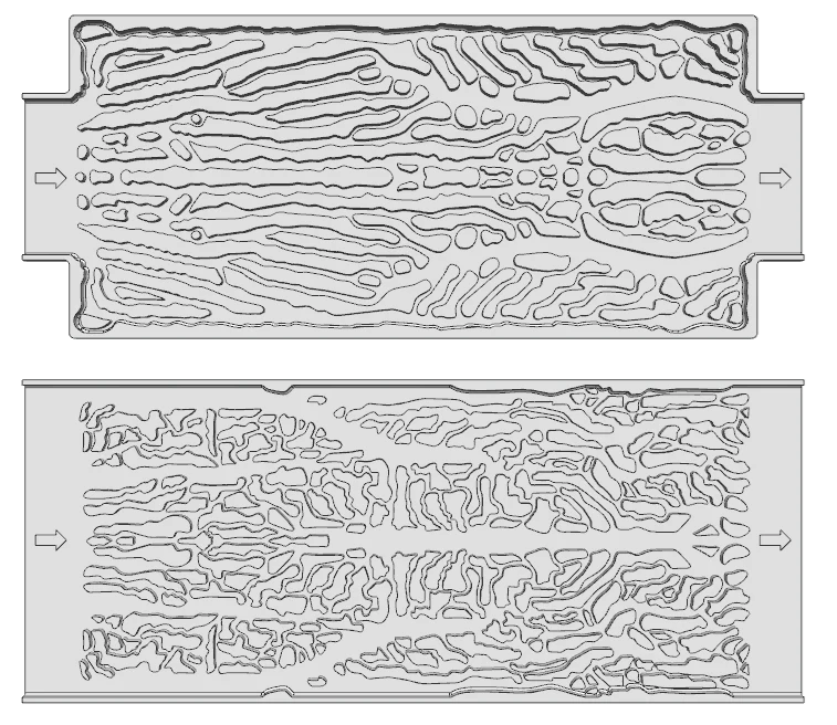
Representative study | screen
Compare coverage, local velocity, maldistribution, and pressure loss under the agreed coolant and boundary conditions.
Representative study | rebuild
Add practical walls, inlet and outlet transitions, powder exits, machining stock, and inspection access.
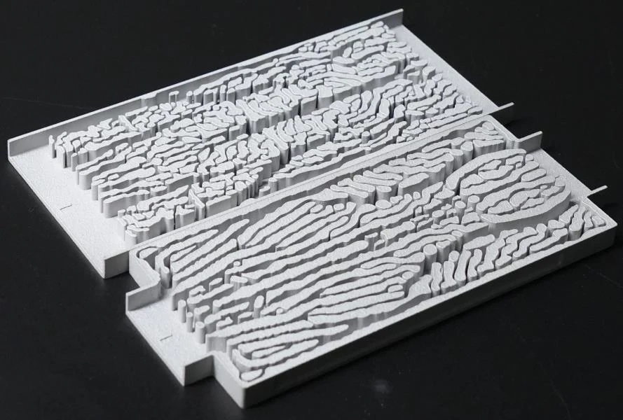
Representative study | verify
Use representative models or builds to challenge feature continuity, access, cleaning, edge conditions, and the planned inspection route.
Source note: the three images above were extracted from BLT partner thermal-management engineering material supplied for publication. They illustrate the optimization-to-reconstruction workflow only; they are not universal performance claims or a finished-part guarantee.
05 | Read the evidence chain
The strongest engineering content is not a single temperature image. It is the progression from coupons to product-scale cores, internal inspection, paired thermal and hydraulic measurements, and a test rig built around the decision variables.
Three periodic-surface families were represented by nine coupons. Formation quality, heat transfer, and flow resistance were reviewed together instead of selecting geometry from simulation alone.
Eight product-scale cores added cell-size variation, S- and U-type flow arrangements, inlet/outlet transitions, CT review, and local manifold optimization. Coupon ranking did not replace product verification.
Printed and machined cold-plate comparisons in the source material showed that a geometry change could improve heat rejection while either increasing or decreasing pressure loss. Both outcomes must be measured.
The referenced bench combined controlled coolant conditioning with flow, pressure, inlet/outlet temperature, and wall-temperature measurement so thermal gain could be assessed against pumping cost.
A unit cell is not approved because it has more area, and an optimization plot is not approved because it looks organic. The route advances only when thermal benefit, pressure loss, flow distribution, build evidence, cleaning, and inspection remain compatible at the relevant scale.
06 | Plan validation before release
Not every project needs every test. The quotation should identify the question, observable, method, acceptance limit, included record, and the party responsible for final system-level thermal verification.
| Question to answer | Observable | Possible method | Customer-facing evidence |
|---|---|---|---|
| Is the specified heat being removed? | Coolant flow and inlet/outlet temperature difference | Calibrated flow and temperature measurements under an agreed heat input | Heat-rejection result with operating conditions and measurement boundary |
| Are hotspots and uniformity controlled? | Wall, interface, or source-region temperature | Thermocouples, resistance sensors, thermal imaging, or an agreed equivalent | Temperature map or defined measurement-point result |
| Is the pumping cost acceptable? | Flow rate, pressure drop, and branch balance | Differential pressure and flow measurement across the relevant circuit | Flow-pressure curve or acceptance-point result |
| Are hidden passages manufacturable and clean? | Continuity, dimensions, residual powder, and accessible cleaning routes | CT, sectioning, borescope, flow comparison, or another agreed inspection | Internal-feature evidence tied to drawing or acceptance criteria |
| Is the pressure boundary acceptable? | Pressure, dwell, leakage, and visible deformation | Project-defined proof, leak, or pressure-decay test | Test record with medium, limit, dwell, and acceptance rule |
Methods are selected by project risk and scope. Listing a method here does not mean it is included in every quotation or that the source studies constitute certification of a new part.
A converged temperature plot is not physical validation. Calculation verification examines numerical behavior; model validation compares predictions with relevant measurements; part acceptance applies the agreed product limits. A prototype can meet its temperature limit while the model still predicts it poorly. Conversely, a model can correctly predict that the part fails.
NASA's CFD validation guidance ties credibility to physical comparisons, numerical checks and the intended range of use. The published scope of ASME V&V 20-2009 (R2021) addresses specified variables at specified validation points with solution and experimental uncertainty. These references inform the review; they do not certify this service or any example on this page.
| Result to compare | Make the comparison valid | Decision and next evidence |
|---|---|---|
| Hotspot temperature | Compare the prediction at the sensor location or defined measurement region, not an unmeasurable model maximum with a remote thermocouple. | Record model-to-test difference, uncertainty and distance to the temperature limit. Revisit source allocation and interfaces if the mismatch matters to the decision. |
| Flow and pressure loss | Match fluid, temperature, flow direction, pressure-tap locations and the part/fixture boundary. Keep fixture losses identifiable. | Investigate geometry, venting, flow distribution or boundary assumptions before using a fitted pressure-loss value to predict a new duty point. |
| Transient or off-design duty | Name the load history, initial state and tested flow/temperature range. Separate measured operating cases from extrapolated predictions. | A successful steady-state point does not release start-up, cycling or another coolant. List the additional evidence needed for the intended use. |
If an uncertain contact or friction parameter is adjusted using a test, label that result as calibration. Preserve the original prediction and check the revised model against additional relevant conditions before treating it as predictive. There is no universal acceptable percentage error: the required confidence depends on the quantity, measurement uncertainty, margin to the limit and consequence of a wrong decision.
For a review, send the model revision, as-tested geometry, raw measurement table, sensor map, operating conditions and the decision that the result must support. We can scope the evidence gap before a new build; simulation, prototype manufacture, testing and customer system qualification must each have an agreed owner. For branch-specific methods, continue to the flow-distribution acceptance guide.
For the handover from design to an accepted part, use the copper LPBF thermal hardware release guide to connect material state, accessible interfaces, internal passages, and the final evidence package.
07 | Define the deliverable
The output is more than a visually complex CAD model. Scope should state what was assumed, which candidates were rejected, why the selected route advanced, what evidence is included, and which system-level questions remain with the customer.
Two project entry points
A design-stage brief starts with losses, temperature limits, coolant, the assembled heat path, envelope, and open assumptions. Build-ready CAD starts with DfAM, material, machining, inspection, and acceptance review. Unknown fields can remain open when they are clearly separated from confirmed requirements.
Submit thermal requirements or CADCommercial paths
Channel, manifold, pressure, leak, sealing, machining, CT, and acceptance requirements.
Open cold plate RFQ pathCompact cores, internal area, pressure drop, powder removal, cleaning, flow, and leak evidence.
Open heat exchanger RFQ pathFin geometry, airflow or coolant conditions, interface flatness, mounting, and thermal validation.
Open heat sink RFQ pathFAQ
No. Convergence and numerical checks support calculation verification. Model validation compares specified predictions with relevant physical measurements, including uncertainty and applicability limits. Product acceptance separately asks whether the finished hardware meets the agreed requirements; a converged model, a good model-to-test match and an accepted part are not interchangeable results.
Yes. A prototype can meet the measured limit at the tested duty while the model predicts it poorly or lacks sufficient evidence. Record the hardware test result separately from model credibility. Do not use that one passing point to guarantee a different heat load, coolant, contact stack or flow range.
Yes. A useful early review can start from the heat load or heat map, temperature limit, coolant, flow or pressure-drop budget, available envelope, ports, and interfaces. The output is a scoped design route, not a guaranteed performance result.
Candidate channels, fins, manifolds, or generated structures are compared under the same defined boundary conditions. Heat transfer, temperature uniformity, flow distribution, pressure loss, pump requirements, manufacturability, and cleaning must be reviewed together.
A machined, brazed, skived, extruded, tube-based, or folded-fin route is normally better when simple accessible geometry meets the thermal, pressure, quantity, inspection, and cost targets. Complexity alone is not a reason to print.
The quotation can define the applicable dimensional, CT, cleanliness, flow, pressure, leak, conductivity, surface, or thermal evidence. The exact methods and acceptance limits must be agreed for the specific part and operating conditions.
A cooling channel is only one part of the assembled heat path. Air gaps, interface resistance, material properties, source allocation, and the location of the cooled surface can redistribute component temperatures even when the channel geometry and total pressure loss remain similar. These assumptions must be version-controlled and reviewed through sensitivity cases.