
Copper LPBF Beyond “Can It Print?”: What It Takes to Release a Real Thermal Part
A field-informed release guide for pure copper, CuCrZr, and GRCop LPBF thermal hardware, covering powder traceability, channels, post-processing, CT, leak, flow, and thermal evidence.
Working on a copper part? Start a project review — share a brief; CAD can follow.
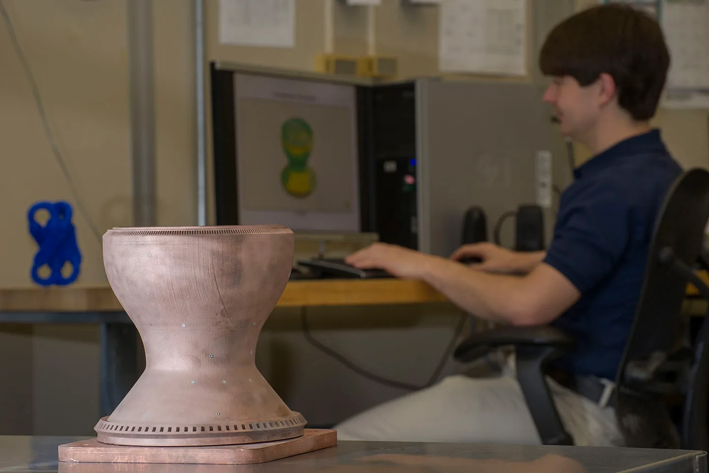
A dense copper coupon is not a qualified heat exchanger. Release evidence must connect the selected alloy and process to representative geometry, powder removal, final material condition, inspection, and the functional tests that match the real service risk.
Cover reference: NASA/MSFC/Emmett Given — a GRCop-84 LPBF copper combustion-chamber liner during structured-light verification. Shown as public engineering evidence, not as a COPPER 3DP customer part.
A successful test piece is not a released cooling plate. A visually impressive lattice is not evidence that a component will meet its pressure-drop, leak-rate, or thermal-cycle requirements.
That distinction appears repeatedly in public discussions among metal additive manufacturing practitioners. In one CuCrZr process-development discussion, an anonymous operator described changing layer thickness and scan conditions, upgrading optical components, and considering a green laser if customer demand justified the investment. The exchange began with a successful test print but quickly expanded into wavelength, optical-system heating, shielding gas, oxidation, productivity, and the economics of production development.
The discussion is anecdotal, but the engineering question is useful. The challenge is rarely one isolated parameter. Material, powder, laser, atmosphere, geometry, post-processing, inspection, and commercial volume form one connected system.
The useful question is therefore not:
Can this supplier print copper?
It is:
Can this specific copper part be manufactured, cleaned, inspected, and released with evidence that matches its service conditions?
This guide organizes that evidence into a practical release chain. Use the quality and acceptance decision path to place it within the wider finished-part evidence framework. It does not replace an application-specific qualification plan, drawing, specification, or approval by the responsible engineering and quality teams.
Begin with the operating requirement, not the alloy name
“Copper” is not a sufficient material specification. Pure copper, CuCrZr, and GRCop alloys solve different engineering problems.
| Material family | Typical reason for selection | Main qualification question |
|---|---|---|
| Pure copper | Maximum electrical or thermal conductivity | Can the required conductivity, material continuity, and internal geometry be produced consistently on the selected route? |
| CuCrZr, including C18150-type material | A strength-conductivity compromise for thermal hardware, electrical components, and cooling structures | Which build and heat-treatment condition produces the required strength and conductivity together? |
| GRCop-42 or GRCop-84 | Elevated-temperature strength and thermal conductivity in high-heat-flux service | Has the complete material-process-orientation-post-processing route been validated for the stated duty? |
These materials should not be treated as interchangeable grades with slightly different data sheets. Pure copper may be attractive when conductivity dominates and mechanical loading is moderate. CuCrZr is precipitation hardenable, so its final property balance depends heavily on thermal history after printing. GRCop alloys were developed for severe high-heat-flux environments and should be evaluated as part of an engineered cooling and structural system.
A buyer should specify the required outcome—conductivity, temperature, pressure, fatigue or cycle expectations, leak rate, and corrosion environment—before asking a supplier to select the alloy. Use the copper alloy selection guide to compare pure copper, CuCrZr, and CuCr1Zr by failure mode rather than by grade name alone.
Why copper process parameters do not transfer cleanly
Copper combines high thermal conductivity with high reflectivity at commonly used near-infrared laser wavelengths. Energy that is not coupled into the powder bed may be reflected, while absorbed heat is conducted away rapidly. This can narrow the useful process window and increase the consequences of changes in the machine, powder, or geometry.
Shorter-wavelength lasers can improve energy coupling for pure copper under suitable conditions, but wavelength alone does not qualify a process. Beam quality, spot size, power stability, scan strategy, layer thickness, recoating, atmosphere, powder condition, and optical protection still matter.
Volumetric energy density is best treated as a bookkeeping value, not a transferable recipe. Two builds with the same calculated energy density can have different melt-pool behavior because power and scan speed are not physically interchangeable.
Recent NIST research on highly reflective metals identified a copper LPBF regime in which absorption increased at scan speeds above 4 m/s at 400 W under the studied conditions. The result challenged the assumption that density must always decrease monotonically as scan speed rises. More importantly, it showed why melt-pool behavior must be measured and validated for the actual process rather than inferred from one energy-density number.
A credible copper LPBF development program should distinguish at least four windows:
- A coupon-density window.
- A stable production window across the usable build area.
- A geometry window covering thin walls, downskins, overhangs, and channels.
- A property window after the specified post-processing route.
Only the fourth window is directly relevant to a released part.
A dense coupon does not represent a thin-wall cooling structure
Bulk density is important, but it is not a complete predictor of component performance. Thin walls experience different heat flow, contour-to-hatch interaction, and dimensional error from a large density cube. Channel roofs introduce downskin behavior. Small cross-sections may also contain a much larger proportion of rough surface and altered microstructure.
One NASA-supported study of vertically built LPBF GRCop-42 tensile specimens reported that reducing specimen thickness from 2.0 mm to 0.7 mm produced a greater than 20% decrease in ultimate tensile strength and nearly a 50% reduction in ductility in both the tested as-built and HIP conditions. This is a study-specific result, not a universal design factor, but it demonstrates why a thick coupon cannot automatically qualify a thin-wall liner. See the NASA size-effects report for LPBF GRCop-42.
For a thermal part, representative qualification features may need to include:
- The minimum production wall thickness.
- Representative channel roofs and downskin angles.
- Contour-to-hatch transition regions.
- Inlet and outlet manifolds.
- Local changes in section thickness.
- Machining stock and attachment features.
- Witness specimens built in relevant orientations and locations.
A supplier quoting only “99.9% density” has not answered whether the actual walls and channels meet the acceptance criteria. The density and conductivity guide explains why those characteristics require separate methods and limits. The qualification-coupon guide covers placement, orientation, and measurement planning.
Powder is a controlled process input, not a commodity
A recurring production problem is the gap between buying powder and controlling powder. In an anecdotal powder-management discussion, an operator wanted a history map connecting received powder, virgin and reused blends, machine loading, storage, and every production job. Replies described custom systems, QR-code workflows, and different reuse strategies.
That field problem mirrors the scope of ISO/ASTM 52907:2019, which covers powder documentation and traceability, sampling, particle-size distribution, chemical composition, characteristic densities, morphology, flowability, contamination, packaging, storage, and requirements for used powder.
For copper and copper alloys, a meaningful powder record should include:
- Supplier, alloy designation, and certificate of analysis.
- Manufacturing or atomization route.
- Powder lot and container identity.
- Particle-size distribution and test method.
- Morphology, including satellites, agglomerates, and irregular particles.
- Apparent or tap density and flowability.
- Oxygen and other controlled chemistry limits.
- Storage and exposure history.
- Sieving or conditioning history.
- Machine and material-contact equipment used.
- Virgin-to-reused blending history.
- Jobs and build cycles connected to the powder lot.
- Samples retained for later investigation.
Powder reuse should not be approved solely because a container has been used fewer than an arbitrary number of times.
A NASA GRCop-42 recycling study completed twelve sequential builds, recovering powder from each prior build and adding virgin powder to refill the machine. Researchers examined morphology, particle-size distribution, flowability, chemistry, tensile properties, and low-cycle-fatigue specimens. Flowability and cohesiveness showed a general decline, while small chemistry variations did not correlate clearly with increasing reuse.
This does not mean GRCop-42 powder is automatically acceptable for twelve cycles. It means reuse decisions should be based on a defined blending procedure, measured powder condition, and corresponding part or witness data. A different machine, exposure history, sieving system, or acceptance requirement may produce a different result.
The best cooling channel can become the worst powder trap
Internal channels are one of the strongest reasons to use copper LPBF. They are also where manufacturability, safety, and inspection problems accumulate.
An older discussion about removing powder from DMLS parts mentioned compressed inert gas, vacuum, vibration, pneumatic tools, part rotation, and purpose-built depowdering equipment. These anonymous field observations do not establish a qualified process. They do show why no single cleaning method fits every geometry.
Depowdering is therefore not merely a shop-floor step performed after the CAD model is finished. It is a design requirement. A channel should be evaluated for:
- Minimum diameter after expected dimensional error.
- Length-to-diameter ratio.
- Changes in direction and cross-section.
- Dead legs and local pockets.
- Downskin roughness and partially fused particles.
- Access for gas flow, vibration, rotation, or inspection.
- The possibility of temporary cleaning ports.
- A measurable criterion for confirming that powder has been removed.
“Powder was blown out until nothing more appeared” is not a strong release criterion for a sealed cooling part.
Depending on risk, verification may require controlled mass comparison, borescope inspection, CT, flow testing, cleanliness testing, or a validated depowdering cycle. If the design prevents meaningful verification, the geometry may need to be divided, reoriented, or provided with temporary access features.
Use the hidden-channel DFM workflow before quotation, then define a measurable powder-removal and cleaning route.
Internal roughness is part of the fluid design
An as-designed channel and an as-built channel are not hydraulically identical. Channel roofs, overhangs, and downward-facing surfaces can accumulate dross or partially fused particles. Surface texture changes effective flow area, friction factor, pressure drop, and heat-transfer behavior. Local dimensional error at a manifold or narrow throat may dominate the performance of the complete component.
NASA compared modeled and empirical hydraulic performance in additively manufactured regenerative cooling chambers. Its regenerative-cooled chamber performance study examined the effects of as-built surface finish, off-nominal flow geometry, and actual flow area on pressure drop and cooling performance across hot-fire test campaigns.
This has two practical consequences:
- CFD should use a defensible representation of manufactured surface condition and dimensions. A smooth nominal channel may produce an optimistic result.
- Pressure-drop and heat-transfer predictions should be correlated with physical flow and thermal tests. Simulation can compare concepts and expose sensitivity, but it does not measure trapped powder, roughness, leakage, or local manufacturing error.
The thermal design and validation workflow shows how to connect boundary conditions, architecture screening, model fidelity, manufacturable geometry, and a validation plan.
A rendering or CFD plot is not release evidence
A recent lattice heat-exchanger discussion provides a compact example of evidence-level confusion. The post presented an intricate lattice heat exchanger and made a pressure-drop comparison. When commenters asked about the basis, the author explained that the displayed geometry had not itself been performance-simulated and that the referenced study was not publicly available.
Nothing in that exchange proves the concept ineffective. It shows that several evidence levels had been blended together:
- A generated geometry.
- A visual rendering.
- A printed object.
- A simulation of a similar structure.
- A performance claim.
- A publicly reviewable test result.
Those are not equivalent.
For a production heat exchanger, useful evidence should identify:
- The exact tested geometry and material condition.
- Fluid, temperature, pressure, and flow range.
- Surface condition and post-processing.
- Measured pressure drop.
- Heat-transfer rate or effectiveness.
- External heat loss and instrumentation uncertainty.
- Leak-test method and acceptance limit.
- Dimensional or CT correlation.
- Repeatability across multiple specimens.
- Comparison geometry and normalization method.
The faster a software tool generates a lattice, the more important it becomes to slow down at the validation stage.
Build orientation is part of the performance architecture
Orientation affects more than support quantity and build time. It may change:
- Grain and crystallographic texture.
- Mechanical anisotropy.
- Channel-roof quality.
- Downskin roughness.
- Residual stress and distortion.
- Accessibility for powder removal.
- Location of supports and witness specimens.
- Machining datums and available stock.
- The feasibility of later joining or jacket deposition.
NASA’s stronger public evidence connects these issues at component level. NASA developed GRCop-42 LPBF parameters, characterized the material, fabricated chambers with integral cooling channels and closeouts, and progressed to substantial hot-fire testing. Its GRCop-42 development report describes a high-conductivity, high-strength copper alloy for high-heat-flux service and reports high-density builds with strength comparable to wrought GRCop-42.
The significance is not simply that NASA printed GRCop-42. NASA connected material development to channels, closeouts, component fabrication, and functional testing. A less extreme thermal component should follow the same reasoning at a qualification level proportional to its risk.
Monolithic is not automatically better
Metal AM is often promoted as a route to part consolidation. Consolidation can remove joints and simplify assembly, but it can also make inspection, cleaning, repair, and material optimization more difficult.
A copper liner may provide thermal performance while a nickel-alloy jacket carries structural load. Inserts may provide threads, wear surfaces, or sealing interfaces. Machined covers may make channels cleanable and inspectable. A brazed or welded assembly may sometimes be easier to validate than a sealed monolith.
NASA has evaluated both monolithic copper chambers and bimetallic architectures, including copper-alloy liners combined with Inconel jackets. See NASA’s monolithic and bimetallic combustion-chamber overview.
Select the architecture by examining:
- Thermal resistance across interfaces.
- Structural load path.
- Differential thermal expansion.
- Joining qualification.
- Leak paths and seal design.
- Inspectability before and after joining.
- Repairability.
- Replacement cost.
- Total production risk.
Part consolidation is valuable only when the consolidated part remains possible to clean, inspect, qualify, and maintain.
Post-processing is part of the material definition
“CuCrZr” does not fully define the delivered material. A complete designation should include the additive process, orientation, and thermal condition.
LPBF produces rapid solidification and repeated thermal cycling. Stress relief, hot isostatic pressing, solution treatment, aging, and machining can change precipitation, residual stress, conductivity, strength, ductility, and dimensions.
Peer-reviewed CuCrZr research by Wegener and colleagues showed that heat treatment can substantially change electrical conductivity, microstructure, and mechanical properties. The appropriate route depends on the required balance rather than on maximizing one property in isolation.
Questions to settle before production include:
- Is stress relief performed before removing the part from the plate?
- Is HIP required, optional, or prohibited?
- What aging or solution-treatment route defines the accepted condition?
- Are dimensions compensated for thermal treatment?
- When are functional surfaces machined?
- Are internal surfaces left as-built or treated?
- Are conductivity and tensile specimens processed with the part?
- Is the same furnace cycle used for qualification and production?
A test certificate that lists only the alloy and density leaves too much of the material state undefined. The CuCrZr heat-treatment guide provides a service-led specification framework.
CT is powerful, but it needs an inspection plan
X-ray computed tomography is valuable because it can inspect internal surfaces and features that lack direct line of sight. A NIST study of optical metrology and XCT used IN625 and 17-4 stainless-steel LPBF specimens to examine complementary surface measurement, including overhangs and undercuts. It is useful general LPBF metrology evidence, not copper-specific proof of defect detectability.
CT capability must be agreed for the actual copper alloy, part size, section thickness, voxel size, scan orientation, target defect, reconstruction method, and acceptance threshold. CT is not an unlimited “proof of no defects.”
The RFQ should define what CT must demonstrate:
- Channel continuity.
- Minimum wall thickness.
- Pore-size or indication limits.
- Absence of blockage.
- Dimensional compliance.
- Comparison with a reference scan.
For some parts, a combination of CT, metallographic witness coupons, dimensional inspection, leak testing, and flow testing provides better coverage than CT alone. Use the cold-plate CT and leak-test guide to set risk-based acceptance criteria.
A practical evidence ladder for copper thermal hardware
The following sequence prevents a design-stage success from being mistaken for a production release.
| Level | Evidence | What it proves—and does not prove |
|---|---|---|
| 1 | CAD, rendering, or topology result | Shows the geometry can be represented, not manufactured |
| 2 | CFD or thermal simulation | Predicts behavior under model assumptions, not as-built performance |
| 3 | Density and parameter coupons | Establishes an initial process window, not representative channels |
| 4 | Representative feature specimen | Tests walls, overhangs, channels, and depowdering access |
| 5 | Material characterization | Establishes chemistry, microstructure, conductivity, and mechanical properties in defined conditions |
| 6 | Dimensional inspection and CT | Checks accessible and internal geometry within the inspection capability |
| 7 | Leak, proof-pressure, and flow tests | Demonstrates containment and hydraulic behavior |
| 8 | Thermal-performance test | Measures real heat transfer and temperature response |
| 9 | Cyclic, fatigue, or duty-representative testing | Addresses durability under repeated service |
| 10 | Controlled production and traceability | Connects released performance to repeatable powder, machine, build, and post-processing records |
Not every component requires all ten levels. A low-pressure prototype and a human-rated propulsion component should not carry the same qualification burden. The release plan should be proportional to failure consequence.
For critical applications, ISO/ASTM 52904:2024, published by ASTM as F3303-24, addresses metal powder-bed-fusion process control for critical applications and test specimens. A standard supplies a framework; the project still needs its own material state, acceptance values, responsibilities, and change controls.
What a useful copper LPBF RFQ should contain
A good RFQ allows the supplier to evaluate the whole manufacturing and release route instead of quoting only build volume and part mass.
Service conditions
- Operating and maximum temperature.
- Internal and external pressure.
- Fluid or gas composition.
- Flow range and allowable pressure drop.
- Number and severity of thermal or pressure cycles.
- Corrosion, vacuum, radiation, or oxidation environment.
- Consequence of leakage or failure.
Material requirements
- Preferred alloy or permission to recommend one.
- Minimum thermal or electrical conductivity.
- Yield, tensile, ductility, or fatigue requirements.
- Required material and post-processing condition.
- Restrictions on HIP, brazing, welding, or coatings.
Geometry and surfaces
- Critical walls and internal channels.
- Minimum permitted flow area.
- Machining datums and final tolerances.
- Internal and external surface-finish requirements.
- Permitted temporary cleaning or inspection ports.
- Areas where supports, joints, or repair are prohibited.
Acceptance and documentation
- Powder certificate and lot traceability.
- Powder-reuse policy.
- Witness specimens and their orientation.
- Density, metallography, or conductivity testing.
- CT scope and detectable-defect requirement.
- Leak rate and test medium.
- Proof or burst pressure.
- Flow and thermal-performance testing.
- Material, build, heat-treatment, and inspection records.
- Nonconformance and deviation-approval process.
The proof, helium-leak, and flow-test guide separates the questions those methods can answer. For multi-passage hardware, add a flow-distribution acceptance test instead of relying on total flow alone.
Questions to ask a copper LPBF supplier
Before placing an order, ask:
- Is the proposed alloy qualified on the exact machine and laser configuration?
- What geometries were included in the qualification—not only density cubes?
- How are thin-wall and channel properties represented?
- How are powder lots, blends, sieving, and reuse traced?
- What is the validated depowdering method for this geometry?
- How is complete powder removal verified?
- Which build orientation is proposed, and what tradeoffs drove it?
- What heat treatment defines the delivered material condition?
- Which properties are tested on every build, every lot, or only during initial qualification?
- What CT resolution is achievable for the proposed size and wall thickness?
- Are leak, proof-pressure, flow, or thermal tests available?
- How are internal roughness and dimensional deviation reflected in hydraulic predictions?
- Which surfaces will be machined, and when?
- If the component uses a jacket or joint, how is that interface qualified?
- What evidence will appear in the final release package?
A supplier does not need to disclose proprietary scan parameters to answer these questions. It does need to explain how the process is controlled and how conformity will be demonstrated.
For rocket-engine or other potentially controlled hardware sourced from China, read the export-compliance and end-user documentation guide before transferring drawings. Manufacturing qualification and permission to export are separate decisions.
If the project is ready for review, start with a legally shareable brief through the copper LPBF RFQ form. Provide CAD only after confirming that its transfer is permitted and any required handling arrangements are in place. Unknown engineering fields can remain open for review.
The real product is released performance
Copper LPBF has moved beyond the question of whether copper alloys can be melted with a laser. Public NASA programs, peer-reviewed CuCrZr research, and modern machine-process development show that useful copper hardware can be produced.
The remaining difficulty is less photogenic: powder history, thin-wall behavior, trapped powder, channel roughness, dimensional error, anisotropy, heat treatment, machining, CT capability, leak testing, hydraulic correlation, and production traceability.
That is also where the commercial value lies.
A buyer should not purchase “3D-printed copper” as an abstract capability. The buyer should purchase a defined material condition, a manufacturable geometry, an inspection plan, and evidence that the delivered component performs in its intended environment.
The best copper LPBF project is not the one with the most intricate internal geometry. It is the one whose geometry can be printed, cleaned, inspected, tested—and confidently released.
Source and evidence note
This article was informed by public Reddit discussions involving metal-AM operators and technically engaged users. Those discussions were used only to identify recurring field problems and questions; they are anecdotal and are not treated as controlled technical evidence.
Technical conclusions were checked against NASA reports, NIST research, ISO/ASTM standards, and peer-reviewed publications linked throughout the article. Application-specific acceptance criteria should still be defined by the responsible engineering and quality teams.
Copper AM quotation
Turn a thermal requirement into a reviewable brief
Describe the heat source, cooling constraints, and decision you need to make. Share existing calculations, sketches, or CAD if available; detailed design and validation scope must be agreed separately.
NDA available on request. We reply within 2 business days.
Before you submit: Thermal design and validation support.
