
Pure Copper 3D Printing: Applications, Benefits, and Manufacturing Challenges
A practical engineering guide to pure copper 3D printing, covering conductivity-driven applications, LPBF process limits, material trade-offs, validation evidence, and RFQ inputs.
Working on a copper part? Start a project review — share a brief; CAD can follow.
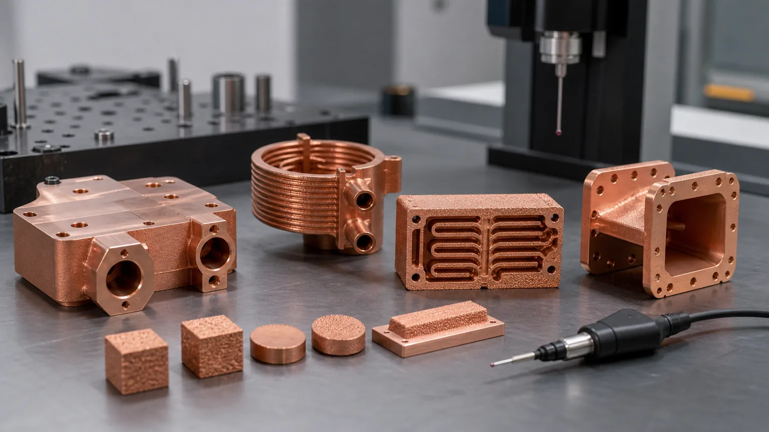
Pure copper 3D printing is valuable when the part needs high electrical or thermal conductivity plus geometry that cannot be produced cleanly by CNC machining, brazing, tube bending, or assembled copper hardware. It is not the default answer for every copper part. The decision should compare the finished component: material route, density, conductivity, geometry, contact surfaces, internal channels, post-processing, inspection, and acceptance evidence.
Pure copper is attractive for one reason: it moves heat and current extremely well.
That same reason creates the manufacturing problem. Copper reflects common infrared laser energy before a stable melt pool forms, and it conducts absorbed heat away quickly after melting begins. In laser powder bed fusion, this can narrow the process window. The result is not that pure copper cannot be printed. The result is that pure copper parts need a qualified route, realistic geometry, and a validation plan that matches the application.
For buyers, the useful question is not “Can you print pure copper?”
The useful question is:
“Can this specific pure copper component be printed, cleaned, machined, tested, and accepted with the conductivity, geometry, surface, and inspection evidence we need?”
Where Pure Copper 3D Printing Creates Real Value
Pure copper additive manufacturing is strongest when conductivity and geometry need to work together.
Industrial material suppliers describe similar application families. EOS positions copper AM around good electrical and thermal conductivity, heat exchangers, electronics, power electronics heat sinks, rocket propulsion systems, and copper coils. Eplus3D lists pure copper for high electrical and thermal conductivity uses such as heat exchangers, induction coils, and high-frequency electronics. Those signals are useful because they match where copper AM usually becomes commercially meaningful.
Good pure copper 3D printing candidates often include:
- High-current conductors with complex routing, cooling, or packaging constraints.
- Induction coil segments with nonstandard geometry or integrated cooling.
- RF and microwave parts where copper conductivity and complex geometry matter.
- Heat spreaders, cold plates, and heat exchanger features with cleanable channels.
- Semiconductor equipment parts that combine thermal control, RF, vacuum, or precision interfaces.
- Prototype and low-volume conductive hardware where iteration speed matters.
The common pattern is not “make every copper part with AM.” It is “use AM where the copper function and the geometry are both valuable.”
If the part is a flat copper plate, simple busbar, rectangular heat spreader, or drilled block, conventional machining may be lower risk. Use When Copper 3D Printing Is Better Than CNC Machining before forcing an additive route.
Benefit 1: Conductivity Where The Geometry Is Complex
Pure copper is the first material to review when maximum conductivity is the dominant function and the part is mechanically calm.
That can mean electrical conductivity in:
- Busbars and compact power distribution blocks.
- Contact blocks with integrated mounting or cooling.
- Induction coils with unusual turn geometry.
- Conductive fixtures or electrodes.
- RF and microwave surfaces.
It can also mean thermal conductivity in:
- Heat spreaders and thermal straps.
- Liquid cold plates.
- Heat exchanger sections.
- Laser, optics, and semiconductor thermal control parts.
- Compact cooling hardware for power electronics.
But conductivity should be specified as a finished-part requirement, not a powder label. Density, porosity, heat treatment, surface finish, machining, oxidation, plating, and contact geometry can change the result. For current-carrying parts, electrical conductivity in 3D printed copper parts should be the companion review because contact resistance can dominate bulk conductivity. If the RFQ is for connector bodies, contact blocks, busbar transitions, electrodes, or other finished current-carrying hardware, use Pure Copper Additive Manufacturing for Conductive Components to define contact pads, current path geometry, plating, and acceptance evidence.
For thermal parts, the same logic applies. A pure copper cold plate can have strong bulk conductivity and still fail because the thermal face is not flat, channels trap powder, ports leak, or the proof-pressure target was not included in the quote. For heat transfer material decisions, see Pure Copper vs CuCrZr for 3D Printed Heat Transfer Parts.
Benefit 2: Integrated Cooling, Current, And Mounting Features
Pure copper AM becomes more interesting when one component can combine multiple functions:
| Function to integrate | Why pure copper AM may help | What must be validated |
|---|---|---|
| Current path plus cooling | Reduces joint count and can move heat away from high-current zones | Conductivity, pressure, leak, cleaning, contact surfaces |
| Heat spreader plus manifold | Puts coolant close to the heat source | Channel access, pressure drop, flatness, leak testing |
| RF surface plus cooling | Combines conductive RF geometry with thermal control | Surface finish, plating, dimensional accuracy, vacuum cleaning |
| Coil geometry plus internal passage | Enables nonstandard induction or heating paths | Turn spacing, insulation, leak, powder removal, conductivity |
| Mounting bosses plus copper body | Reduces assembly interfaces | Thread strength, machining stock, clamp load, material state |
This integration is the reason copper AM can win. It is also the reason early RFQ scope matters. A printed blank is not the same as a finished conductive component with machined pads, pressure test, cleaning record, conductivity coupon, and CMM report.
For internal channels, the quote should connect pure copper material choice with powder removal challenges in copper internal channels, LPBF design rules, and tolerance planning.
Manufacturing Challenge: Pure Copper LPBF Needs A Qualified Route
Copper’s best properties also make laser powder bed fusion difficult.
EOS states that copper was historically difficult to print because reflectivity and high thermal conductivity made conventional 3D printing problematic. The difficulty is practical, not theoretical:
- Too little effective energy can create lack-of-fusion porosity.
- Rapid heat conduction can make thin features and heavy sections behave differently.
- Aggressive parameters can create spatter, rough surfaces, distortion, or unstable tracks.
- The process route can affect density, conductivity, and repeatability.
- The finished part may still require cleaning, machining, stress relief, polishing, plating, or testing.
Green-laser systems are one route used to improve copper energy coupling. TRUMPF’s TruPrint 1000 Green Edition material notes describe a 515 nm green laser system for highly reflective materials such as copper and copper alloys, with pure copper examples including inductors, heat exchangers, and electronics. That does not make every pure copper geometry easy. It means the machine route, parameter set, material, and validation evidence must be part of the manufacturing review.
For a deeper process explanation, use Why Copper Is Difficult to 3D Print with Standard Infrared Lasers.
When Pure Copper Is The Right First Choice
Pure copper should usually be reviewed first when:
- Maximum electrical or thermal conductivity is the main performance driver.
- Mechanical loads are modest or carried by thicker sections.
- Contact pads, datums, sealing lands, and threaded features can be machined after printing.
- Internal channels are large enough and accessible enough for powder removal and inspection.
- The supplier can show a validated pure copper route for the machine and process.
- The buyer can define conductivity, surface finish, pressure, or dimensional acceptance targets.
Pure copper is often a good early direction for heat spreaders, low-load conductive blocks, simple cooled electrical hardware, RF or microwave components with defined finishing, and prototype conductivity studies.
The word “prototype” still deserves care. A prototype pure copper part can answer a serious engineering question, but only if the quote includes the evidence needed to interpret the result. A printed part with no density, conductivity, surface, pressure, or flow evidence may not explain why the test passed or failed.
When CuCrZr Or CuCr1Zr May Be Safer
Pure copper is not automatically better because it has the strongest conductivity argument.
CuCrZr or CuCr1Zr may be safer when the finished component must handle:
- Threaded ports near internal channels.
- Pressure boundaries with thin walls.
- Clamp-loaded contact faces.
- Repeated assembly or torque cycles.
- Fragile fins, bosses, or mounting lugs.
- Heat treatment and coupon-based material evidence.
- A drawing or customer requirement tied to a copper-chromium-zirconium route.
3D Systems describes CuCr1Zr(A) as a high-conductivity, high-strength copper alloy for applications that need both strength and thermal or electrical conductivity, including heat exchangers, electrical components, conductive contacts, and induction coils. EOS also describes CuCrZr as combining electrical and thermal conductivity with good mechanical properties after heat treatment.
The important point is not that CuCrZr or CuCr1Zr is always superior. It is that mechanical reserve can protect the actual copper function. A slightly lower-conductivity alloy that holds flatness, threads, pressure, and tolerances may outperform a pure copper part that distorts, leaks, or develops poor contact resistance.
For the full material gate, use Copper Alloy Selection for Metal 3D Printing: Pure Cu vs CuCrZr vs CuCr1Zr and Heat Treatment for CuCrZr 3D Printed Components. If the drawing or supplier qualification calls out CuCr1Zr by name, review CuCr1Zr Copper Alloy 3D Printing for Industrial Components before treating it as a generic CuCrZr substitute.
If the design already shows strength-driven risks such as threaded ports, clamp-loaded faces, thin pressure walls, repeated assembly, or coupon-based material evidence, review CuCrZr 3D Printing: When Strength Matters More Than Maximum Conductivity before insisting on pure copper.
Application Review By Part Type
High-Current Conductors And Busbars
Pure copper AM can help when the conductor also needs compact routing, integrated coolant, mounts, or three-dimensional packaging. It is weaker for simple flat busbars that can be cut, punched, bent, or CNC machined.
The RFQ should include continuous current, peak current, duty cycle, temperature-rise limit, contact pad geometry, clamping method, plating requirement, and any insulation or clearance constraints. If the part contains internal cooling, include coolant, pressure, leak, cleaning, and flow targets. The adjacent guide is Copper Busbars and Induction Coils RFQ Guide.
Induction Coils
Pure copper is attractive for induction coils because current path, cooling, and compact turn geometry can all matter. AM can support coil paths that are hard to machine or bend from tube, but the coil still needs enough spacing, cleaning access, and finishing allowance.
Specify frequency, current, duty cycle, coolant, pressure, turn spacing, insulation plan, leak test, and contact surfaces. Do not assume the as-built surface is acceptable for every coil interface.
RF And Microwave Parts
RF hardware can value pure copper conductivity, but surface finish and dimensional control often become the limiting factors. A printed waveguide, cavity, or microwave structure may need machining, polishing, plating, cleaning, and CMM inspection. For this path, connect the RFQ to 3D Printed Copper RF Waveguide and Vacuum Components and Plating and Finishing Copper AM Parts.
Thermal Management Parts
Pure copper is attractive for heat spreaders, cold plates, and compact heat exchangers when bulk conductivity and channel geometry both matter. The risk is assuming that smaller channels always improve the final result. Channels must be printable, cleanable, inspectable, and compatible with pressure and flow requirements.
Use Microchannel Cold Plates in Thermal Management, Liquid Cooling Plate Design with Copper AM, and 3D Printed Copper Heat Exchanger Limits when the part depends on coolant passages.
Semiconductor Equipment Parts
Semiconductor equipment can combine several copper AM drivers: thermal control, RF surfaces, vacuum sealing, high-current hardware, cleanliness, and compact packaging. Pure copper may be useful when conductivity dominates, but final cleaning, leak testing, sealing lands, and inspection evidence often decide whether the part can be accepted.
Use Copper AM Parts for Semiconductor Equipment and the RF Vacuum Manifold Design Review when the part also carries cleanliness, vacuum, or RF requirements.
Validation Evidence Buyers Should Request
Pure copper AM projects should define evidence before price comparison.
Useful evidence can include:
- Material route: pure copper grade, powder route, machine platform, and process state.
- Density or porosity evidence when conductivity, pressure, or fatigue risk matters.
- Conductivity test method and whether it is coupon-based or part-based.
- Surface finish on contact, RF, sealing, or thermal faces.
- CMM report for datums, port locations, flatness, and critical geometry.
- CT, borescope, flow, pressure, or leak tests for internal channels.
- Cleaning and drying method for fluid or vacuum parts.
- Heat treatment or stress relief record if used.
- Plating, polishing, or passivation scope if relevant.
For pure copper, the absence of validation does not only create technical risk. It also creates quote risk. Suppliers must either add assumptions or price conservatively for rework, inspection, and iteration.
For finished-part planning, review Copper AM Surface Finish Options and Post-Processing Methods for 3D Printed Copper Parts.
Cost Drivers For Pure Copper 3D Printing
Pure copper AM pricing is controlled by more than part volume.
The main drivers are:
- Material and machine route for pure copper.
- Build orientation, supports, and thermal management during printing.
- Failed-build risk when geometry is aggressive.
- Powder removal from internal channels.
- CNC machining stock on contact pads, datums, ports, and sealing faces.
- Polishing, plating, cleaning, or vacuum handling.
- Conductivity, density, CMM, leak, pressure, flow, CT, or surface reports.
- First-article learning when the geometry is new.
That is why two quotes can both say “pure copper 3D printing” while covering different scopes. One may be a printed blank. The other may be a finished, cleaned, machined, inspected, and tested copper component. For pricing review, use Cost Drivers in Copper 3D Printing Projects.
RFQ Checklist For Pure Copper AM Parts
Send these inputs when requesting pure copper 3D printing:
- STEP or native CAD plus a 2D drawing.
- Application: thermal, electrical, RF, vacuum, semiconductor, tooling, or test hardware.
- Material preference: pure copper required, pure copper preferred, or open to CuCrZr review.
- Required conductivity target and test method if known.
- Current, voltage, duty cycle, heat load, pressure, flow, RF band, or vacuum conditions.
- Critical surfaces: contact pads, thermal faces, RF surfaces, sealing lands, datums, and threads.
- Surface finish, flatness, roughness, plating, and machining requirements.
- Internal channel section views, cleaning access, and pressure or leak criteria.
- Required evidence: conductivity, density, CMM, CT, leak, pressure, flow, hardness, or cleanliness.
- Quantity, revision stage, target lead time, and acceptable design-review flexibility.
If the material is not fixed, say so. “Review pure copper first, but recommend CuCrZr if threads, pressure, or flatness risk dominate” is a strong RFQ instruction. It gives the supplier room to protect the finished component instead of defending a material keyword.
Practical Verdict
Pure copper 3D printing is a high-value route when maximum conductivity and complex geometry both matter. It can support compact conductors, induction coils, thermal hardware, RF and microwave structures, and semiconductor equipment parts that are difficult to manufacture as simple machined or brazed assemblies.
It is also a demanding route. Reflectivity, high thermal conductivity, density control, internal channel cleaning, contact-surface finishing, and validation evidence must be treated as part of the manufacturing plan.
Use pure copper when conductivity is the main job and the component can be printed, cleaned, machined, and inspected realistically. Review CuCrZr or CuCr1Zr when threads, pressure, clamp load, thin walls, heat treatment, or qualification evidence matter more than the last increment of conductivity.
For a first review, send CAD, drawings, quantity, material preference, current or heat load, pressure or RF requirements, critical surfaces, and acceptance criteria to info@szcomo.com, or organize the package through the copper AM RFQ checklist.
Related reading: Electrical Conductivity in 3D Printed Copper Parts, Copper Alloy Selection for Metal 3D Printing, CuCr1Zr Copper Alloy 3D Printing for Industrial Components, Why Copper Is Difficult to 3D Print with Standard Infrared Lasers, and Post-Processing Methods for 3D Printed Copper Parts.
Copper AM quotation
Need to choose a copper material for a part?
Describe the part, operating environment, and properties that matter. State the material preference only if decided; material state and acceptance can be reviewed together.
NDA available on request. We reply within 2 business days.
Before you submit: Copper materials and delivered condition.
