
3D Printed Copper Cooling Plates: Microchannel Design Guide
When 3D printed copper cooling plates beat machined or brazed routes, and how to specify cleanable microchannels, pressure drop, leak testing, and RFQ acceptance.
Working on a copper part? Start a project review — share a brief; CAD can follow.
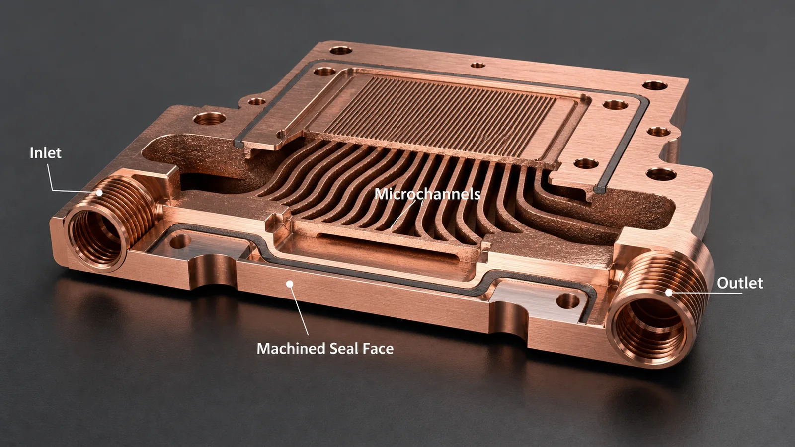
Copper 3D printing is a strong candidate for microchannel cold plates when heat flux, package height, manifold routing, or leak-path reduction cannot be solved cleanly with CNC machining or brazing. The trade-off is clear: tighter thermal geometry usually adds powder-removal, pressure-drop, machining, inspection, and cleaning cost.
Most microchannel cold plate projects start with the same pressure: the heat source gets smaller, the power density climbs, and the available envelope does not grow with it.
A compact channel network can look convincing in simulation while leaving the manufacturing questions unanswered: how will powder leave the longest passage, which internal surfaces remain as-built, and how will the finished part be tested at the intended flow rate?
Copper additive manufacturing can place channels close to the heat source, merge manifolds into one body, and remove brazed interfaces that would otherwise become leak or thermal-resistance risks. But the printed route is not a shortcut around physics. It moves the project into a different ledger: build orientation, minimum wall thickness, trapped powder, internal roughness, post-machining, leak testing, and flow verification all become part of the quote.
The Open Compute Project cold plate workstream treats coolant compatibility, interfaces, leakage, qualification, and serviceability as system-level requirements. Copper AM changes how the internal body can be manufactured; it does not remove those cold plate requirements.
If the project is already ready for supplier review, use the 3D printed copper cold plate RFQ page as the commercial entry point, then use this article to refine microchannel geometry, powder removal, pressure drop, leak testing, and acceptance criteria.
Choose your next step: Submit CAD or an early-stage thermal brief if you need a quotation review. If the heat load, flow budget, or test scope is still open, start with thermal design validation and boundary conditions. Unknown values can be marked as open; do not turn assumptions into purchase requirements.
The Process Window: What Actually Controls the Design
For microchannel cold plates, the question is not only “Can copper 3D printing make this shape?”
The better question is:
Can the printed copper body meet thermal, flow, leak, flatness, and cleanliness requirements after all post-processing is finished?
That distinction matters because the printed geometry is only the beginning. A useful copper AM cold plate often needs:
- LPBF build review for channel geometry and support strategy.
- Stress relief or heat treatment when required by the alloy and process route.
- CNC machining for sealing faces, mounting datums, ports, threads, and contact surfaces.
- Powder removal and internal flushing.
- Pressure, leak, and flow checks.
- CMM or flatness inspection on critical interfaces.
- Optional CT review for first articles or high-risk internal networks.
A simple cold plate may be cheaper and faster as a machined and brazed assembly. Copper 3D printing earns its place when the internal geometry changes the thermal result or reduces a real assembly risk.
Why Microchannels Push Teams Toward Additive Manufacturing
Microchannels can increase wetted surface area and move coolant closer to the heat source. In dense electronics cooling, that can reduce temperature gradients across a base and improve local heat extraction.
The value is strongest when conventional manufacturing creates a compromise:
| Constraint | Conventional route pressure | Copper AM opportunity |
|---|---|---|
| Package height | Brazed stack or cover plate may add thickness | Monolithic body can reduce assembly height |
| Port location | Drilled channels prefer straight access | Curved channels and manifolds can route around keep-outs |
| Heat-source density | Machining may limit channel placement | Channels can sit closer to local hot spots |
| Leak risk | Brazed joints add potential leak paths | Fewer joints can reduce leak interfaces |
| Prototype iteration | Tooling or joining process may slow changes | CAD-driven internal changes can be reviewed faster |
This does not mean printed cold plates always win. Reject or redesign a printed route when the channel network cannot be cleaned, when pressure-drop risk exceeds the thermal benefit, or when a brazed plate meets the requirement with lower cost and a simpler inspection plan.
That is the honest decision point. Copper AM is strongest when geometry freedom has a measurable job.
Hard Limits That Should Be Reviewed Before Quotation
Microchannel cold plates fail quietly when the RFQ focuses on the outside envelope and hides the internal channel risk.
A practical first review should check:
- Minimum channel width and height.
- Minimum wall thickness between channels.
- Channel length-to-diameter ratio.
- Bend radius and branch count.
- Inlet and outlet access for powder removal.
- Internal surface roughness tolerance.
- Working pressure and proof pressure.
- Leak acceptance method.
- Contact-face flatness as a drawing tolerance tied to interface area, clamp conditions, and the thermal interface material; do not substitute a generic plus/minus dimension for a flatness requirement.
- Surface finish on the heat-transfer interface, often controlled separately from as-printed internal surfaces.
A visually successful internal channel network is not evidence of cleanliness. Agree a cleaning and verification plan using appropriate flush records, particle criteria, internal inspection, and flow checks. A blocked branch can escape external visual inspection, and neither a CT image nor a flow result alone proves that all contamination has been removed.
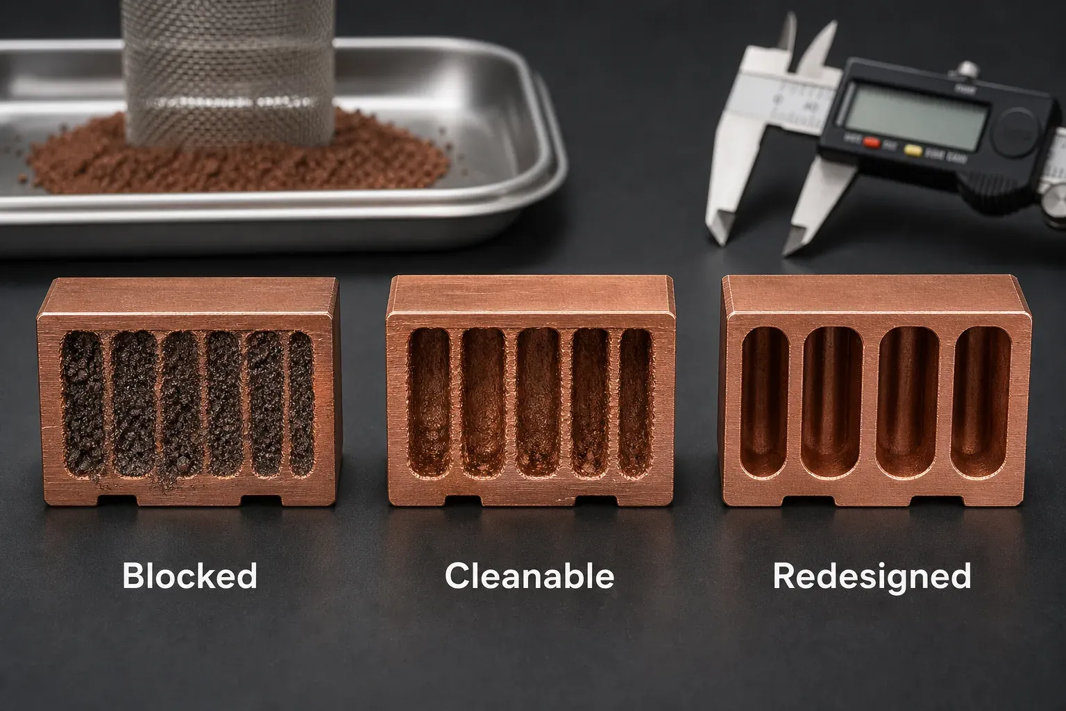
Figure 2. Concept illustration, not inspected production specimens. Powder-removal access and cleaning verification must be reviewed independently of the outside dimensions.
Channel Size Is Not Only a Thermal Variable
Thermal models often reward narrow channels because they increase surface area and local heat transfer. Manufacturing adds a second curve.
As channel size drops, powder retention, relative roughness, pressure loss, and inspection uncertainty become more important. There is no universal minimum cleanable passage for every LPBF copper cold plate. Review the smallest finished section together with its length, bends, orientation, branch transitions, and available powder exits; an isolated hole diameter does not describe a complete channel network.
The right trade-off depends on coolant, flow rate, heat flux, pressure budget, alloy, build orientation, and acceptance method. A larger passage may ease cleaning and lower hydraulic resistance, but its thermal result must be compared at the same operating conditions before selecting it.
| Review gate | What the drawing or review should identify | Evidence before release |
|---|---|---|
| Smallest passage | Finished section, length, bends, branches, and orientation | Representative build and agreed internal-feature inspection |
| Powder-removal route | Accessible exits, flushing direction, and dead-end risks | Cleaning procedure and project-defined cleanliness evidence |
| Hydraulic performance | Coolant condition, test ports, operating flow, and allowed loss | Flow-pressure measurements with fixture loss accounted for |
| Thermal performance | Heat-source map, interface stack, inlet temperature, and limits | Defined temperature measurements under the agreed heat input |
| Pressure boundary | Working conditions, proof and leak requirements, seals, and ports | Separate test methods, limits, and records as specified |
Manufacturing cleanliness is only the first gate. If the installed loop can introduce corrosion products, seal debris, hose particles, biological material, or service contamination, use the microchannel cold plate clogging and filtration guide to connect the vulnerable passage, filter performance, commissioning flush, hydraulic baseline, and maintenance trigger.
If a model optimizes thermal performance without cleaning access or as-built flow uncertainty, extra flushing, inspection, or redesign can change the preferred route. Treat those constraints as design inputs rather than post-build surprises.
Illustrative Design-Review Scenario: Dense Cold Plate for a Power Electronics Module
The following is a hypothetical review workflow, not a customer case or a report of measured test results. Consider a copper cold plate for a compact power electronics module with a curved microchannel field beneath the heat source and a compact internal manifold.
Before comparing candidates, record:
- Heat-source footprint, heat input, and permitted component temperatures.
- Coolant composition, inlet temperature, operating flow range, and available pump head.
- Pressure-drop allowance across the part, with fixture and external-loop losses distinguished.
- Drawing-defined contact flatness, surface finish, clamping, and interface material.
- Working pressure plus separately agreed proof and leak methods, limits, and test conditions.
- Candidate material and final state, with machined sealing and mounting surfaces identified.
If a first-article flow test later shows more pressure loss than the model, do not immediately attribute the difference to printing. First check coolant temperature and properties, instrument calibration, pressure-tap locations, fixtures, fittings, and trapped air. Then investigate as-built sections, internal roughness, local restrictions, and cleaning evidence.
A discrepancy is a question to investigate, not evidence of one predetermined failure mode.
Depending on that evidence, candidate revisions could include:
- Enlarging restrictive sections and rechecking the heat-transfer trade-off.
- Simplifying low-value branches while checking local flow distribution.
- Improving cleaning access through the port geometry.
- Reviewing build orientation against powder exits and channel quality.
- Machining accessible inlet and outlet regions where the drawing requires it.
- Repeating flow checks and thermal measurements under the same defined conditions.
These revisions may improve manufacturability but can reduce theoretical surface area or add machining and test steps. No reduction in pressure loss or temperature is claimed for this example; the revised design would need its own evidence before release.
The lesson is to optimize the accepted component, not only the simulated channel network.
The Cost Ledger: Where the Quote Actually Changes
Procurement teams sometimes compare printed copper cold plates against machined parts using only unit price. That misses the real cost structure.
For microchannel cold plates, the quote is usually shaped by:
| Cost driver | Why it matters | Typical decision impact |
|---|---|---|
| Channel complexity | More branches and tighter passages increase cleaning and inspection risk | May trigger redesign before quote |
| Copper material route | Pure copper and CuCrZr have different conductivity, strength, and process behavior | Changes thermal and mechanical assumptions |
| Build orientation | Affects supports, distortion, channel quality, and powder exit | Can change both yield and lead time |
| CNC finishing | Sealing faces, ports, threads, and datums usually cannot remain as-printed | Adds setup and inspection cost |
| Leak or pressure test | Fluid parts need acceptance beyond dimensions | Adds fixture and test time |
| CT inspection | Useful for high-risk first articles but not free | Adds cost and interpretation limits |
| Cleanliness requirement | Filtered flush, drying, and packaging may be required | Changes post-processing route |
Separate one-time fixture and qualification costs from recurring part costs. A pressure or flow fixture needs defined port connections, seals, instrumentation, and test conditions. Ask whether the quotation includes fixture development, repeat use, calibration, and the first-article report; the appropriate scope depends on quantity and the acceptance plan.
When Copper 3D Printing Is the Right Choice
Choose copper additive manufacturing for a microchannel cold plate when at least one of these conditions is true:
- The coolant path must curve around keep-out zones or package constraints.
- The manifold needs to be integrated into the plate instead of assembled.
- Heat flux is localized and channels need to sit close to the source.
- Brazed joints create unacceptable leak, thermal cycling, or reliability concerns.
- Prototype iterations require internal geometry changes that are hard to machine.
- The cold plate also integrates mounting, electrical, sensor, or structural features.
Avoid forcing the printed route when:
- The plate is flat with simple straight channels.
- The port layout is easy to machine.
- The only goal is lower unit cost.
- The internal channels have no powder-removal path.
- The design requires smooth internal surfaces but provides no finishing access.
- Leak testing is required but no pressure or acceptance method is defined.
This is not a rejection of AM. It is process discipline.
Readiness Check Before Sending the RFQ
Before asking for a price, check whether the RFQ package answers these questions.
- What is the heat source size, location, and heat load?
- What coolant will be used?
- What is the required flow rate or pressure-drop limit?
- What are the working pressure and proof pressure?
- Which surfaces need machining, flatness, or surface-finish control?
- Are inlet and outlet ports fixed, or can they change for cleaning and testing?
- Is CT inspection expected, or are flow and pressure testing enough?
- Is the part a prototype, qualification unit, or repeat production order?
- Is pure copper required, or is CuCrZr acceptable for strength and thread stability?
A weak RFQ says: “Please quote this 3D printed copper cold plate.”
A stronger RFQ says: “Please review the attached copper cold plate for our water-glycol loop. The requirement sheet identifies coolant composition, inlet temperature, flow and pressure-drop targets, working pressure, ports, and interface tolerances. Please separate machining, cleaning, first-article flow testing, and leak verification in the quotation. Open items are marked for review.”
The second request identifies the required inputs without inventing universal limits. Proof pressure, dwell, test medium, and allowable leakage must be agreed for the part and applicable requirements; a pressure multiplier is not a substitute for that review.
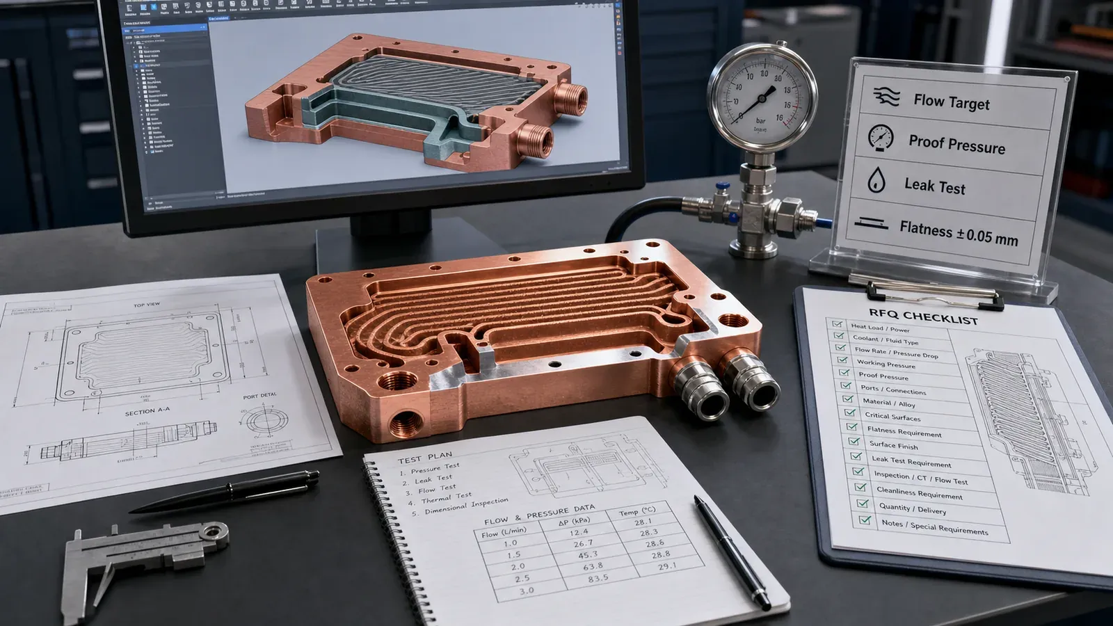
Figure 3. Illustrative RFQ planning scene, not a test record. Define heat load, coolant, flow, pressure, surfaces, inspection, and cleanliness before final quotation.
Practical Design Guidance
Start with the thermal problem, then build the manufacturing route around it.
For early-stage microchannel cold plates, we usually recommend:
- Keep the first channel network less aggressive than the CFD optimum.
- Leave cleaning and inspection access through practical port geometry.
- Separate machined surfaces from as-printed internal surfaces.
- Define pressure, leak, and flow acceptance early.
- Treat CT as a targeted first-article tool, not a universal substitute for flow and leak testing.
- Compare the printed route against CNC or brazing when the geometry is not clearly AM-driven.
The tool limit is important: CT can help identify internal blockage or trapped powder risk, but it does not automatically prove thermal performance, leak tightness, or cleanliness. Flow and pressure tests still matter because they test the function directly.
Related Decision Paths
If this is the first cold plate review, use the broader liquid cooling plate design guide to compare routing, manifolds, and assembly risk before focusing only on microchannels. For larger cores, the 3D printed copper heat exchanger guide explains where pressure drop, cleaning, and leakage change the manufacturing route.
For quotation details, pair this page with powder removal for copper AM internal channels, CT and leak test criteria for copper cold plates, and the 3D printed copper cold plate RFQ checklist. Those pages help turn a thermal concept into a quote-ready package.
Before approving a first article, use the copper LPBF thermal hardware release guide to connect material state, finished interfaces, internal-channel evidence, and drawing-defined acceptance. It complements the geometry review here; density alone does not release a functioning cold plate.
FAQ
Is copper 3D printing always better for microchannel cold plates?
No. It is better when the internal channel geometry, compact manifold, joint reduction, or heat-source layout creates value that CNC machining or brazing cannot match cleanly. If the plate uses simple straight channels and accessible ports, conventional machining or brazing may be lower cost and lower risk.
What is the biggest mistake in a microchannel cold plate RFQ?
The most common mistake is sending only the outside CAD shape without defining flow, pressure, leak, cleaning, and interface requirements. The outside geometry may be printable while the internal channel network remains difficult to clean or verify.
Does copper AM internal roughness hurt thermal performance?
It depends. Roughness can increase surface area and turbulence, but it can also raise pressure drop, trap particles, and reduce repeatability. The RFQ should state whether thermal transfer, pressure drop, cleanliness, or inspection confidence is the controlling requirement.
What is the minimum channel size for a 3D printed copper cold plate?
There is no single minimum that guarantees printing, powder removal, cleanliness, and flow performance for every geometry. Review the finished passage section, length, bends, branches, build orientation, material route, and cleaning access together. Agree representative build and inspection evidence before fixing a critical minimum on the drawing.
Should every printed copper cold plate receive CT inspection?
Not always. CT can be valuable for first articles, new channel networks, and high-risk internal geometry. For stable production, flow testing, pressure testing, leak testing, and dimensional inspection may provide better practical control. The inspection plan should match the failure mode.
What files should be sent for quotation?
Send STEP or native CAD, a drawing if available, heat load, coolant, flow target, pressure limits, material preference, critical surfaces, port requirements, quantity, and inspection or cleanliness expectations. If values are still open, state the assumptions.
Verdict
Copper 3D printing is a strong route for microchannel cold plates when the design needs compact internal geometry, integrated manifolds, reduced joints, or hot-spot cooling that conventional routes cannot provide without compromise.
It is a weak route when the design is simple, the pressure-drop budget is unclear, the channels cannot be cleaned, or the RFQ does not define acceptance.
The practical recommendation is straightforward: use copper AM for the geometry it uniquely enables, then budget for the finishing and verification that make the cold plate usable.
Submit your cold plate CAD or thermal brief for review, or email info@szcomo.com. Include quantity and the known thermal, coolant, pressure, surface, and inspection requirements. An early review can start with open items; the final quotation and acceptance plan must resolve the requirements that control the part.
Copper AM quotation
Review a copper cold plate or cooling part
Describe the cooling problem and available space. Add a sketch or CAD, coolant, heat load, and flow or pressure limits where known; leave open requirements for review.
NDA available on request. We reply within 2 business days.
Before you submit: Custom copper cold plate service.
