
3D Printed Copper Busbars and Induction Coils: RFQ Guide
Specify 3D printed copper busbars and induction coils by current path, duty cycle, contact faces, integrated cooling, insulation, plating, conductivity, and inspection.
Working on a copper part? Start a project review — share a brief; CAD can follow.
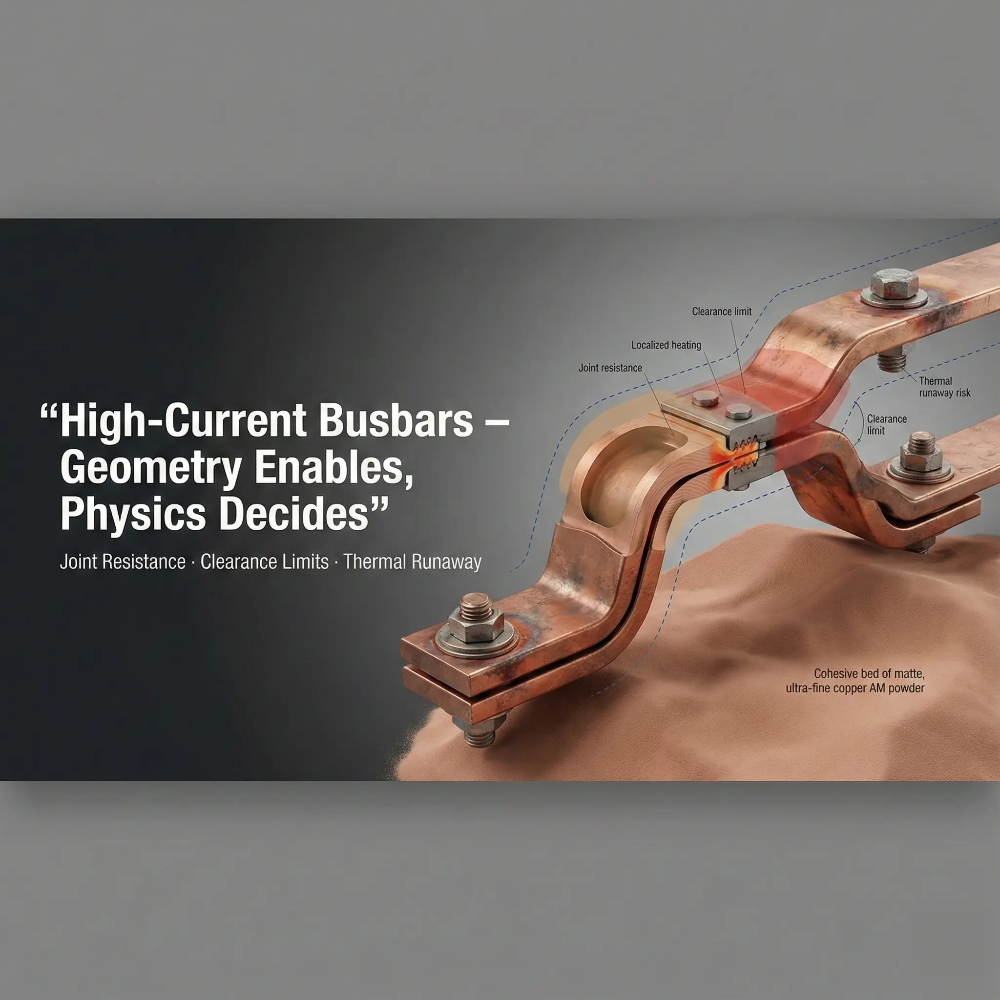
3D printed copper busbars and induction coils are worth reviewing when current path, thermal control, compact routing, or integrated cooling cannot be handled cleanly by flat copper, bent bar, tube, brazed parts, or CNC machining. The RFQ should define the electrical function and acceptance requirements first, then the geometry.
If the project is already defined, use the dedicated 3D printed copper busbar RFQ page or 3D printed copper induction coil RFQ page. This guide explains the shared electrical, cooling, surface, and inspection decisions behind both part types.
Industrial equipment suppliers identify the same geometry-driven applications. EOS lists induction coils among CuCrZr applications, while TRUMPF describes green-laser copper AM for conductive inductors and heat exchangers. These examples show application feasibility, not a universal material or performance guarantee for every drawing.
Why Electrical Copper Parts Need a Different RFQ
Electrical copper hardware is not only a shape. The quote depends on current path, contact resistance, heat generation, insulation distance, surface finish, plating, cooling, and inspection.
For busbars, the risk often sits at joints and contact planes. For induction coils, the risk often sits in local overheating, cooling path reliability, and spacing between turns. For high-voltage or RF hardware, surface condition and field concentration may become the dominant issue.
That is why a STEP file alone is often not enough for a confident quote.
When Copper AM Is Useful for Busbars
Most busbars should be simple. Flat, bent, stamped, laminated, or machined copper is often the right route. Copper AM becomes more interesting when the design has a real 3D constraint.
Useful AM drivers include:
- Compact routing around keep-outs, cooling hardware, or dense packaging.
- Integrated liquid cooling or local heat-spreading features.
- Multiple mounting, sensing, or structural features consolidated into one copper body.
- Prototype or low-volume development where tooling is not attractive.
- Geometry that would otherwise require many joints, bends, or assemblies.
AM is weaker when the requirement is only a flat conductor with simple holes and contact faces. In that case, conventional copper fabrication is usually the cleaner quote route.
When Copper AM Is Useful for Induction Coils
Induction coils may justify copper AM when the coil needs geometry that is difficult to form from tube or machined copper.
Good candidates include:
- Compact coil paths with changing cross-section.
- Internal cooling channels integrated near the heat source.
- Local thickening around high-current or high-heat zones.
- Repeatable coil geometry where hand forming creates variation.
- Integrated mounting, sensor, or fluid connections.
The main caution is that printed copper still needs a practical finishing, cleaning, and inspection route. If the cooling path cannot be cleaned or pressure-tested, the printed concept may not be a good production route.
RFQ Inputs for Copper Busbars and Coils
| Input | Busbar relevance | Induction coil relevance |
|---|---|---|
| Current and duty cycle | Sizing, heating, contact resistance | Heating, cooling load, duty factor |
| Contact faces | Machining, flatness, plating, bolt pattern | Power connection faces and repeatability |
| Cooling requirement | Integrated channels or heat spreading | Flow path, coolant, pressure drop, leak risk |
| Insulation requirement | Creepage, clearance, coating, isolation | Turn spacing, fixture insulation, cooling isolation |
| Material preference | Pure copper vs CuCrZr trade-off | Conductivity vs stability and strength |
| Surface finish and plating | Joint resistance and corrosion control | Contact faces, oxidation, cleaning |
| Quantity and lead time | Route and nesting economics | Prototype vs repeat production approach |
| Inspection | Dimensional, conductivity, contact surfaces | Pressure/leak, flow, dimensional, thermal checks |
If you do not know every value, send the known operating condition and highlight what is critical.
Contact Surfaces Drive the Quote
For busbars, the printed geometry may be complex, but the final performance often depends on simple machined surfaces.
State these clearly:
- Contact face location and size.
- Flatness and surface finish requirement.
- Hole pattern and bolt or clamp approach.
- Plating or coating expectation.
- Whether electrical testing or resistance measurement is required.
Do not assume an as-printed surface is acceptable for a high-current contact. Contact faces usually need machining, cleaning, and sometimes plating.
Cooling and Pressure Requirements
If the part includes internal cooling, the RFQ should define:
- Coolant type and flow rate if known.
- Working pressure and proof pressure.
- Pressure drop target or limit if relevant.
- Leak test method or acceptance if required.
- Cleaning and drying expectations.
For a cooled busbar or coil, the cooling requirement can be more important than the outside shape. A geometry that prints successfully can still fail the project if it cannot be cleaned, sealed, or tested.
Insulation, Creepage, and Clearance
Electrical parts need spacing information. This is especially important when copper AM is used to fit conductors into a compact volume.
Include:
- Voltage level and insulation system.
- Required creepage and clearance if already defined.
- Adjacent conductive or grounded surfaces.
- Coating, sleeve, potting, or fixture assumptions.
- Edge radius or surface finish requirements for field-sensitive areas.
If the design is high-voltage sensitive, review the separate guide on 3D printed copper high-voltage electrodes.
Material and Post-Processing
Pure copper may be preferred for conductivity, but CuCrZr may be useful when strength, threaded features, clamp stability, or temperature exposure matter. The material choice should follow the operating condition, not only the word “copper” on the drawing.
Use Pure Copper 3D Printing: Applications, Benefits, and Manufacturing Challenges when the first question is whether pure copper AM is the right route for the conductor, coil, or contact block before comparing alloys. If the RFQ is already about a finished pure copper conductive component, review Pure Copper Additive Manufacturing for Conductive Components to define contact pads, 3D current paths, plating, conductivity evidence, and component-level inspection.
If a busbar, coil, or contact block has clamped pads, threaded terminals, internal cooling channels, pressure boundaries, or repeated assembly requirements, review CuCrZr 3D Printing: When Strength Matters More Than Maximum Conductivity before locking the material to pure copper. In those projects, a slightly lower-conductivity route can be safer if it protects contact geometry and assembly reliability.
If the drawing or customer specification names CuCr1Zr, use CuCr1Zr Copper Alloy 3D Printing for Industrial Components to define the supplier route, heat-treatment state, coupon evidence, and substitution policy before treating it as a generic CuCrZr option.
Post-processing can include:
- Stress relief or heat treatment.
- Machining of contact faces, holes, and reference datums.
- Polishing or surface conditioning where needed.
- Plating or coating.
- Pressure, leak, flow, conductivity, or dimensional inspection.
Use the materials overview when the alloy is not fixed.
Go/No-Go Review Before Quoting
Good fit for copper AM:
- 3D routing solves a real packaging issue.
- Integrated cooling reduces assembly or thermal risk.
- Contact surfaces are reachable for machining.
- Internal channels can be cleaned and tested.
- Quantity and acceptance scope justify the route.
Weak fit for copper AM:
- Flat conductor geometry with simple holes.
- Very large low-complexity copper parts.
- Contact faces cannot be machined or plated as required.
- Internal cooling paths have no cleaning or leak-test plan.
- Electrical acceptance is undefined.
Related Electrical and Finishing Guides
For the baseline electrical decision, start with Electrical Conductivity in 3D Printed Copper Parts before defining current path, contact resistance, surface finish, and testing. If the buyer is specifically asking for pure copper, review pure copper 3D printing applications and limits and the pure copper conductive components guide before locking the route. For material review, use Copper Alloy Selection for Metal 3D Printing, CuCr1Zr Copper Alloy 3D Printing for Industrial Components, and Pure Copper vs CuCrZr for 3D Printed Heat Transfer Parts when conductivity, strength, documentation, and thermal cycling compete. If the conductor uses internal cooling, review powder removal for copper AM internal channels before finalizing channel size and port access.
For functional surfaces, use Copper 3D Printing Surface Finish Options and Plating and Finishing Copper AM Parts to define contact pads, masking, plating, and inspection. High-voltage designs should also be checked against the 3D printed copper high-voltage electrode feasibility guide.
Practical RFQ Email
For a busbar or induction coil quote, send CAD, drawing, quantity, target lead time, current, duty cycle, contact faces, cooling requirement, insulation constraints, material preference if known, and inspection requirements.
Send files to info@szcomo.com. A simple part can be quoted with stated assumptions. If the electrical or cooling requirement is unclear, expect focused clarification before quote.
Copper AM quotation
Is copper AM a fit for your part?
Describe the part, its job, and the question holding up your decision. Add quantity and critical requirements if known; CAD can follow.
Before you submit: Copper AM capabilities and review scope.
