
Copper Induction Coils: Traditional Manufacturing vs 3D Printing
How copper induction coils are made and how they work—and when printed current paths and cooling channels justify replacing bent tube or brazed assemblies.
Working on a copper part? Start a project review — share a brief; CAD can follow.
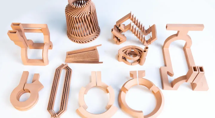
3D printing is a better choice for a copper induction coil when it removes a real constraint: a failure-prone joint in the active head, an awkward cooling path, or a complex heating face that is difficult to reproduce. It does not create a different heating principle, and it is not automatically better than a simple, well-made copper-tube coil.
For an industrial buyer, the useful comparison is not “old technology versus new technology.” It is a qualified fabricated coil versus a qualified additively manufactured coil, delivering the same accepted heating process.
This guide covers industrial work coils for induction heating, brazing and hardening—not small PCB inductors or domestic cookware. It separates published third-party results from our recommended procurement and validation approach. For a defined project, use the copper induction coil manufacturing review.
Cover: reference copper geometries reused from this site’s existing image library. These are not identified as the specimens tested in the studies below. The operating-principle diagram is an original explanatory illustration, not a simulation.
How does a copper induction coil work?
The power supply drives alternating current through the coil. The resulting changing magnetic field induces circulating currents in the conductive workpiece. Electrical resistance converts that induced current into heat inside the workpiece, without needing electrical contact between coil and part. A useful analogy is a transformer: the work coil acts as the primary, and the workpiece behaves as a short-circuited secondary. Ambrell’s explanation of coil operation describes this energy-transfer mechanism.
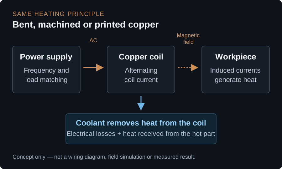
Copper is used for the conductor because low electrical resistance limits unwanted losses in the tool. That does not make the coil loss-free. Its own electrical losses, plus heat received from the hot workpiece, create a cooling load. Industrial coils commonly have water passages through their copper body. The goal is to heat the workpiece while keeping the tool within its qualified thermal limits—not to make a copper element glow and transfer heat by contact. Fluxtrol’s inductor design and cooling discussion explains these coupled loads.
Why the exact shape matters
At operating frequency, current does not distribute uniformly through the copper. Skin and proximity effects influence where current concentrates; the heating pattern also depends on workpiece geometry, coil spacing and magnetic flux control. A material conductivity certificate alone cannot describe this behavior. Fluxtrol’s design reference connects current distribution with the coupling gap and local geometry.
The practical consequence: compare the complete working assembly, not just its external envelope. A replacement can fit the mounting holes yet heat a shoulder differently, put more load on a terminal, or present a different electrical load to the generator.
Printing changes the shapes that can be manufactured. It does not change electromagnetic induction.
How were copper induction coils made before metal 3D printing?
There were—and still are—several conventional routes. “Traditional” does not necessarily mean an imprecise, hand-bent tube.
1. Forming a hollow copper tube
For accessible geometries, a fabricator cuts and bends copper tubing around a mandrel or fixture to form a helix, pancake, hairpin or shaped loop. Round, square and rectangular sections serve different designs. The bore provides a ready-made coolant passage. Forming must avoid flattening or closing it.
Copper work-hardens during deformation; intermediate annealing can make further bending practical. Ambrell’s coil design guide, particularly its coil-forming section, describes annealing and temporary internal support during forming. These are workshop processes requiring proper cleaning and inspection afterward—not permission to leave filler in the cooling circuit.
2. Machining and assembling copper components
Complex heads can instead use machined copper segments, shaped faces, drilled passages and fabricated connections. Sections are joined where necessary to create the current path and enclosed cooling route. Brazing joins the copper with a filler metal; it is not the same operation as melting the whole copper body in a powder bed.
Modern conventional manufacture includes CNC turning and milling, and sometimes wire EDM or waterjet cutting. eldec describes both its conventional and printed inductor production. Precision machining remains an important alternative, not a process that AM has made obsolete.
3. Finishing and qualifying the assembly
The complete tool needs terminals, mounting references, coolant connections and any specified insulation or flux concentrators. Geometry is then checked and heating performance established on the intended equipment. Ambrell describes coil fabrication together with application testing.
Our procurement recommendation is to record the approved coil geometry, interface dimensions, coolant behavior and process outcome—not merely keep a physical master whose condition may change. This applies to fabricated and printed coils alike.
What changes when the coil is 3D printed?
Instead of building the active head from available tube and separate copper details, a designer can define the conductor and its internal passage together in CAD. Metal AM builds that body layer by layer. This can reduce joint count and allow the coolant passage to follow a shaped heating face.
It is a manufacturing chain, however, not a “press print and install” operation. A sensible review sequence is:
- Define the process to preserve. Record the workpiece, heating zone, generator, operating frequency, loading motion, cycle and current tool’s failure mode.
- Design the conductor and coolant passage together. Check local wall thickness, bend transitions, turn separation, machining access, build orientation and powder exits. Preserve functional interfaces unless changes are explicitly accepted.
- Choose a documented material/process route. Identify the exact copper grade, powder specification, build procedure and final material state. Do not substitute one copper alloy for another without review.
- Plan the finishing sequence before printing. Removal from the build, accessible support removal, any qualified heat treatment, machining, cleaning and assembly must leave the intended final geometry.
- Release the tool against agreed evidence. Dimensional, material, hydraulic and electrical checks precede controlled heating trials and production acceptance.
This sequence is our engineering review framework. Its purpose is to expose incomplete scope before either party commits to a production quotation.
LPBF, electron-beam printing and sinter-based routes are not interchangeable
Laser powder bed fusion (LPBF, also called PBF-LB/M) selectively melts metal powder. Copper needs a process suited to its optical and thermal behavior. Green-laser systems are one demonstrated route for pure copper; TRUMPF’s copper-printing announcement identifies conductive inductors as an application. A laser wavelength is not, by itself, a finished-coil guarantee.
GH Induction documents electron-beam powder-bed manufacture of copper coil heads. Metal material-extrusion routes followed by debinding and sintering have also been demonstrated: a 2023 copper-inductor study reports component-scale cooling and heating tests, while identifying shrinkage, porosity and process-dependent conductivity as important issues. Those results do not make a copper-filled desktop filament equivalent to a qualified metal coil.
Ask which route is quoted. Do not transfer a lifetime, pressure or conductivity claim from one route to another.
A printed head does not mean a completely joint-free tool
The active head may be monolithic while the complete assembly still has adapters, terminals or joined connections. GH’s published manufacturing sequence includes brazing the printed coil to an inductor body, followed by finishing and verification.
Ask which joints disappear, which remain, and where the remaining joints sit relative to electrical, thermal and mechanical loading. “No brazing in the active head” is a more useful specification than an unqualified “no joints.”
Where can 3D printing produce a better induction coil?
The strongest opportunity is to change a geometry that conventional fabrication forces the designer to accept. These are candidate advantages, with corresponding proof obligations:
| Decision | Conventional route | Potential AM value | Evidence to request |
|---|---|---|---|
| Shaped heating face | Bend tube or machine segments | Reproduce a complex contour with fewer assembly steps | Gap and heating-pattern verification |
| Internal cooling | Tube bore or joined machined passages | Route cooling through difficult transitions | Cleanliness and flow versus pressure drop |
| Active-head joints | Braze selected details together | Remove selected joints from highly loaded regions | Joint map, leak checks and cycling |
| Replacement consistency | Controlled tooling, machining and assembly | Reuse a released CAD/build/finishing definition | First-article and repeat-build comparison |
| Machine interfaces | Established terminals and adapters | Integrate features where access permits | Fit, contact surfaces and generator compatibility |
| Maintenance | Repair or replace fabricated sections | Replace a repeatable head or qualified module | Repair policy, replacement cost and lead time |
Cooling should follow the failure mechanism
Do not optimize only total flow. A tool can pass a large amount of coolant while leaving a small, highly loaded region poorly cooled. Conversely, making a passage larger can leave too little copper where electrical or mechanical loading requires it.
Our recommended design review overlays four questions: where current concentrates, where heat enters the copper, where coolant removes it, and where cyclic deformation is constrained. Treat the external heating face and internal passage as a coupled design, then verify the manufactured result. Use the existing powder-removal and channel-cleaning guide before accepting a closed passage.
Magnetic flux concentrators are separate components
A flux concentrator redirects the magnetic field; it is not simply another piece of copper. Its material, placement, attachment and cooling still need attention on a printed coil. Fluxtrol explains how magnetic controllers alter the field and heating pattern. Printing the copper body does not automatically replace these components.
Likewise, coil cooling water and the workpiece’s quench delivery have different jobs. In induction hardening, heating and the subsequent quench must both be validated. eldec distinguishes the copper inductor from the quenchant shower, which can itself use a different manufacturing process and material.
What published results actually demonstrate
JTEKT: copying the drawing was not enough
JTEKT’s 2025 engineering report describes a Cu-Zr LPBF development for automotive induction hardening. The first printed version followed the conventional drawing but had 11% lower coolant flow, attributed to roughness and distortion at the channel roof. After shaping and internal-channel optimization, the report measured 24% more flow than the brazed reference.
For its reported production application, heating performance met the product requirements; coil life increased from 29,000 to 150,000 shots. These are the report’s particular material, geometry and process results—not a COPPER 3DP test, a universal life multiplier, or specifications for a different coil. The lesson is the development sequence: identify a weakness, redesign for the manufacturing route, then validate the heating process.
EFD Induction/Danfoss: compatibility was a design constraint
An IFHTSE 2022 paper by Ivanov and Olsen, proceedings pages 313–320 examined a copper coil used to braze connections to a valve body. The redesign addressed thermal and mechanical stresses while retaining compatibility with the existing heating recipe and converter. The printed head was still brazed to an adapter.
The authors reported 210,000 heating cycles without failure at the time of writing, compared with an approximately 9,000-cycle average for the original coil. The improved coil was still operating: 210,000 was an observed run count, not a measured end-of-life limit or a general guarantee. This is evidence for that optimized assembly, not proof that printing any existing CAD file will deliver the same improvement.
Across both examples, the defensible advantage is design freedom used to solve a measured problem, followed by system-level validation.
Material conductivity is necessary, but it is not the whole specification
Pure copper may be the starting point when conductor losses dominate. A copper alloy may be considered where strength, temperature exposure or dimensional stability changes the trade-off. Define the actual grade and final condition; “printed copper” is insufficient.
Request conductivity evidence with the measurement method, test temperature, specimen location and heat-treatment condition. Then separate that material measurement from the operating coil’s AC losses and terminal behavior. See the finished-copper conductivity guide for the material evidence, and the copper-alloy selection guide for grade/state decisions.
As a buyer, do not accept “higher density,” “green laser,” or “higher IACS” as substitutes for a heating trial. A highly conductive body with an unsuitable current path or poorly finished terminal can still be the wrong tool.
When is a traditional coil still the better choice?
Keep the established route when a simple tube coil already holds the required shape, cools adequately and has satisfactory service life. A short replacement lead time and straightforward repair may be worth more than consolidating a small number of low-risk connections.
AM is also a weak candidate if its passages cannot be cleaned, critical surfaces cannot be finished, or the supplier cannot provide an agreed validation route. Changing manufacture is unlikely to fix failures caused primarily by workpiece collisions, poor coolant maintenance or incorrect setup unless those causes are addressed too. Fluxtrol’s coil maintenance guidance identifies mechanical damage, overheating and concentrator attachment as distinct failure concerns.
For a simple loop, request a conventional quote as the baseline. For a repeatedly failing shaped head, request a redesign proposal with explicit success criteria. These are different purchasing exercises.
Compare cost per accepted production cycle, not just coil price
Our recommended commercial comparison uses the same production period, workload and acceptance criteria for both routes:
Coil-related cost per accepted part = (tool purchases + repairs + allocated qualification + changeover/downtime cost + coil-related scrap or rework) / accepted parts.
Use the factory’s actual accounting boundaries and avoid double-counting scrap or lost production. If one cycle processes several parts, record that conversion explicitly. Add energy only when it is metered on a comparable system boundary and normalized to the same accepted output.
A higher-priced printed head can be attractive if it reliably reduces replacement frequency or expensive stoppages. It may be unattractive when the existing coil is inexpensive, quickly repaired and rarely fails. Before ordering, agree what result ends the trial: insufficient life improvement, an unacceptable heating pattern, excessive development cost, or a maintenance burden that outweighs the benefit.
How to qualify a printed replacement coil
The following is a proposed acceptance framework, not a claim that all tests are included in every COPPER 3DP quotation. Set limits with the equipment owner and responsible process engineer.
| Release gate | What to check | What it does not prove |
|---|---|---|
| Geometry and assembly | Heating face, gap, terminals, datums, clearance and loading motion | A good fit does not prove a correct heat pattern |
| Material and finishing | Grade, final state, conductivity evidence and contact surfaces | A coupon does not certify every hidden wall |
| Internal passage | Cleaning records; suitable inspection where required | CT does not replace cleanliness or leak testing |
| Hydraulic integrity | Agreed proof/leak test; flow and pressure drop at defined conditions | Pressure survival does not establish cooling adequacy |
| Electrical integration | Generator/load compatibility, connections and insulation | Low DC resistance does not prove correct AC loading |
| Process outcome | Temperature/time pattern; application-specific hardening or brazing acceptance | One successful cycle does not establish service life |
| Durability | Representative cycling, inspections and defined failure criteria | A test stopped without failure is not a lifetime limit |
Keep workpiece material, initial temperature, fixture position, gap, motion, cooling supply and process settings controlled during comparison. If the printed design needs a new recipe, report that openly instead of presenting the result as a drop-in replacement.
For hardening, the acceptance plan may include hardness distribution, case depth, microstructure and distortion. For brazing, it may include joint integrity and the customer’s leak or strength requirements. These are workpiece outcomes, separate from the coil’s own water-tightness.
Electrical matching deserves early attention. The working head and its leads contribute to the load presented to the tank circuit, as described in Ambrell’s coil design guide. Installation and powered trials belong with qualified induction-equipment personnel, not an uncontrolled bench swap.
What to send for a useful induction-coil RFQ
You do not need a finished AM redesign to start. Send the available information and mark unknowns as pending:
- The job: workpiece drawing/material, target heating zone, process and acceptance requirement.
- The machine: generator model, operating frequency, power/current if known, cycle and duty, scan/rotation or loading motion, and existing interface drawing.
- The current tool: CAD or dimensioned drawing, photos, material if known, flux concentrator/insulation arrangement, service-life records and failure location.
- Cooling: coolant, inlet temperature, available flow and pressure, return conditions, connector details and water-quality constraints.
- Deliverable scope: head only or complete assembly; who owns the electromagnetic design, machining, assembly, commissioning and production validation.
- Commercial constraints: first-article quantity, replacement demand, required delivery, repair strategy and the cost of the current problem.
For a manufacturing review, start with the copper induction coil application page or submit a project brief. CAD can follow. Ask for the proposed material route, finishing scope and acceptance plan alongside price—not an unsupported promise that AM will multiply coil life.
Common questions
Can a printed coil work on my existing induction heater?
Potentially, but matching mounting points is not enough. Confirm electrical loading, terminals, cooling, clearances and process results. Preserve the existing recipe only if testing supports it.
Are all traditional coils full of weak brazed joints?
No. Some simple coils use continuous tubing; others use carefully engineered machined and joined assemblies. Count and locate the actual joints before claiming consolidation will improve reliability.
Can a printed copper coil be repaired?
Sometimes. Repairability depends on failure location, wall condition, access and a qualified repair procedure. Ask whether repair restores the approved dimensions and performance, and which tests follow it. Do not assume either unlimited repair or mandatory disposal.
Does 3D printing always reduce energy consumption?
No. Separate machine input energy, energy absorbed by the workpiece, losses in the coil and cooling-system demand. Compare energy per accepted output under equivalent conditions. A smoother cooling path or longer service life is not, on its own, a measured energy saving.
Is copper suitable for induction even though it is not ferromagnetic?
Yes—the copper work coil carries the supply current and creates the field. Whether a particular workpiece heats effectively is a separate coupling and process-design question. The coil’s job must not be confused with domestic cookware compatibility.
Sources and scope
Sources were reviewed on 10 October 2026. Links beside the relevant claims lead to manufacturer engineering references and research reports. The two numerical case summaries describe third-party applications; no customer drawing, company identity from a private inquiry, or unverified COPPER 3DP performance result is included. The decision tables, cost framework and RFQ checklist are our engineering synthesis, not a published standard or a guaranteed service specification.
Copper AM quotation
Discuss a copper induction coil project
Share the workpiece, heating task, and coil envelope. Add frequency, power, cooling conditions, and a sketch where available.
NDA available on request. We reply within 2 business days.
Before you submit: Copper induction coil service.
