
Tolerances and Dimensional Accuracy in Copper Metal 3D Printing
Specify copper AM tolerances by feature and delivered state, with an acceptance-record example covering flatness, measurement uncertainty, inspection access, and internal-channel limits.
Working on a copper part? Start a project review — share a brief; CAD can follow.
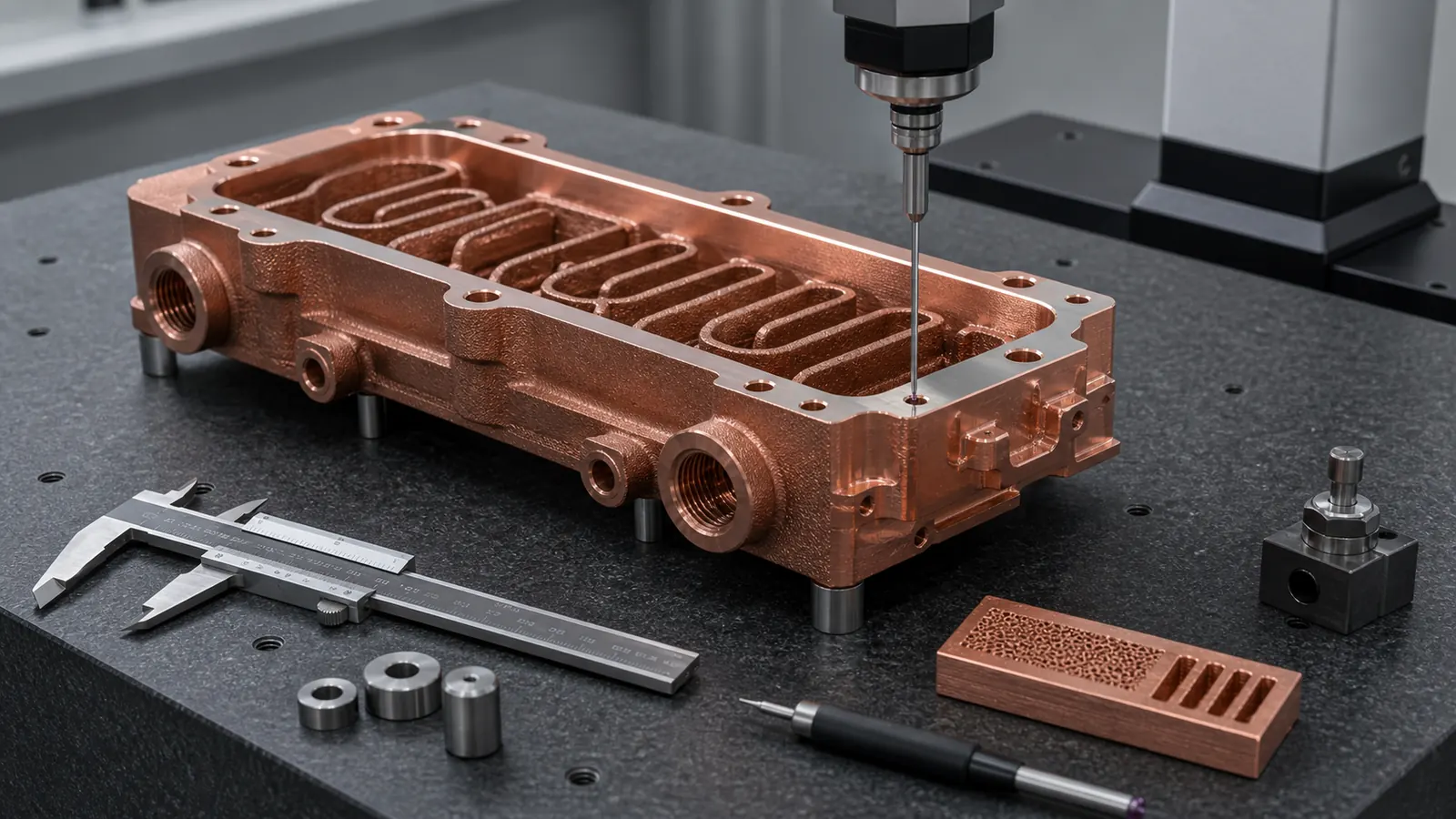
Tolerances in copper metal 3D printing should be assigned by function. A printed copper part may need loose near-net envelope control, tight machined datum control, and functional acceptance tests on the same drawing. The RFQ becomes clearer when the buyer separates as-built geometry, post-machined interfaces, and inspected performance evidence.
Image note: the cover and metrology illustrations are AI-generated concepts, not inspection photographs or evidence of a demonstrated tolerance.
The most expensive tolerance mistake in copper AM is asking every surface to behave like a CNC-machined copper block.
It usually appears as a simple drawing note:
General tolerance: +/-0.05 mm unless otherwise specified.That note may be normal for a small machined copper plate. It becomes weak for a copper LPBF part with internal channels, threaded ports, seal lands, flat thermal faces, support-side surfaces, and thin walls. The supplier must guess which dimensions are critical, which can be machined, which are only near-net, and which are hidden inside the part where a normal CMM cannot reach.
For thermal, electrical, RF, and semiconductor hardware, a correct outer envelope is only one requirement. A seal land can leak, a contact pad can fail to seat, or a machined thread can approach a hidden channel too closely. These local interfaces need their own acceptance requirements.
The Tolerance Question Is Not One Number
The useful question is not “what tolerance can copper 3D printing hold?”
The useful question is:
Which features are acceptable as-built, which must be machined, and what geometric and functional evidence is required for each?
Those are different control systems.
| Tolerance category | Typical features | Better control method |
|---|---|---|
| As-built LPBF geometry | Noncritical exterior walls, support-side surfaces, fins, bosses before machining, rough internal surfaces | Build orientation, support strategy, allowance, process route, visual and dimensional screening |
| Post-machined interfaces | Datum pads, flat thermal faces, O-ring lands, gasket faces, threaded ports, bolt holes, RF flanges, electrical contact pads | CNC finishing, stock allowance, fixture plan, CMM, roughness, thread gauge, flatness check |
| Functional acceptance | Internal channels, pressure boundary, flow path, leak tightness, thermal contact behavior, conductivity route | Flow, pressure, leak, CT, borescope, section coupon, roughness, hardness, conductivity, first article records |
If the drawing applies one number to all three categories, the quote will contain hidden assumptions. A datum-referenced position tolerance on a machined bolt pattern differs from a size tolerance on an as-built fin. Pressure or flow testing also answers a different question from measurement of a hidden wall. Do not substitute one for the other without an agreed acceptance basis.
For the manufacturing foundation, pair this page with Design Rules for Copper Laser Powder Bed Fusion Parts and How to Prepare CAD Files for Copper Metal 3D Printing.
Why Copper Accuracy Is A Finished-Component Problem
Copper adds two tolerance risks to the usual metal AM discussion.
First, the process window is demanding. NIST research on highly reflective metals in LPBF is a useful reference point because copper’s reflectivity and thermal behavior affect how energy enters and stabilizes the melt pool. That does not mean copper cannot be printed. It means dimensional repeatability depends on qualified parameters, geometry, build orientation, heat history, and post-processing route.
Second, copper AM parts are normally selected for difficult geometry. The value is not a rectangular block. It is a cold plate with curved channels, a compact heat exchanger, a waveguide with integrated cooling, a liquid-cooled conductor, or a semiconductor thermal-control part. These features create local heat-flow differences during printing and local movement risk during stress relief, heat treatment, support removal, and machining.
That is why the tolerance plan should follow the finished part, not the print model alone.
Two narrower decisions often need their own review. Use the channel-to-port tolerance stack guide when a machined port, bore, thread, counterbore, or face approaches a hidden channel. Use the copper LPBF datum and inspection-feature guide when the open question is how the functional datum system will survive build, thermal processing, plate removal, machining, and final inspection.
What to Request Instead of a Universal Tolerance Range
This guide does not publish a blanket copper LPBF tolerance or machining allowance. A useful capability statement identifies the feature, size, material and delivered state, manufacturing route, and measurement evidence. An isolated brochure range does not establish capability on the part being quoted.
| Feature or surface | Evidence to request before agreement | What usually controls it |
|---|---|---|
| As-built exterior envelope | Comparable geometry measured in the same delivered state, with actual deviations and method | Size, orientation, supports, thermal history and measurement method |
| Machined datum pad or bolt hole | Proposed datum/fixture plan and feature-level inspection after finishing | CNC setup, stock, part stiffness and access |
| Flat thermal contact face | Surface extent, free or restrained condition, flatness method and separate roughness requirement | Processing sequence, footprint, clamping and measurement coverage |
| Threaded coolant port | Thread specification, gauge or measurement plan, and remaining wall review | Boss geometry, tool access, fitting and pressure boundary |
| O-ring land or gasket face | Controlled seal geometry and texture plus separately defined leak acceptance | Seal design, finishing route and assembly conditions |
| Internal channel dimension | Demonstrated inspection access or an explicitly agreed alternative acceptance route | Attenuation/size limits for CT, section representativeness and functional test coverage |
| Thin fin or pin field | Feature definition, sampling/coverage and damage criteria | Orientation, distortion, handling and measurement accessibility |
A stronger drawing identifies every feature that controls assembly, sealing, contact, pressure, RF performance, or heat transfer. Noncritical regions can use less demanding requirements where the design permits; there is no prescribed number of critical features.
This fits the logic of ISO/ASTM 52911-1, which treats laser-based powder bed fusion of metals as a process-specific design problem. The standard is not a copper tolerance table, but it reinforces the correct behavior: design requirements should reflect the AM process, not only the CAD ideal.
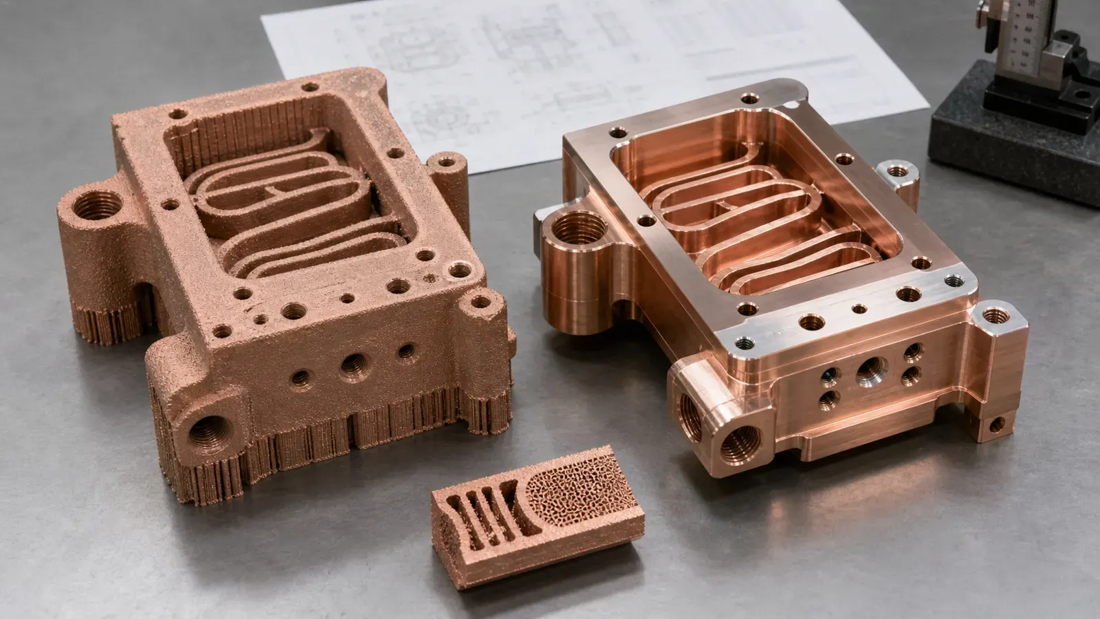
Figure 2. The printed blank and the finished copper component are different tolerance states. The RFQ should make both visible.
Separate The Printed Blank From The Finished Copper Component
A copper AM quote should define at least two geometries:
- The printed blank.
- The finished component.
The printed blank may include support scars, oversized faces, pilot holes, sacrificial pads, unmachined exterior walls, and extra stock near sealing regions. The finished component is what the buyer installs.
For many copper parts, the finished component needs machining on:
- Thermal interface faces.
- Datum pads.
- O-ring grooves and gasket lands.
- Threaded ports and fitting seats.
- Bolt holes and locating holes.
- Electrical contact pads.
- RF mating flanges or conductive surface paths.
- Tube interfaces and manifold ports.
Machining stock provides material for cleanup; it does not guarantee a final tolerance. Agree it against the finished model, distortion risk, build orientation, thermal processing, and fixture access. Verify the remaining channel wall and port geometry after the planned material removal rather than copying a generic allowance.
Without stock, the supplier has only two poor options: accept the as-built surface or machine deeper than planned and risk wall thickness, channel exposure, or seal failure.
Feature-By-Feature Tolerance Strategy
The tolerance plan should follow each feature’s job.
| Feature | Weak RFQ language | Stronger RFQ language |
|---|---|---|
| Thermal contact face | ”As printed, +/-0.05 mm” | Machine after stress relief; define flatness, roughness, datum, and inspection method |
| O-ring groove | ”Print groove to final size” | Machine groove and land; define gland geometry, surface finish, pressure or leak test |
| Threaded coolant port | ”Print thread” | Print robust boss, then drill, tap, or machine thread; define fitting and proof pressure |
| Bolt pattern | ”General tolerance applies” | Define hole size, positional tolerance, datum reference, and machining route |
| Internal channel | ”Hold channel +/-0.05 mm” | Define minimum passage, longest path, cleaning access, pressure drop, flow, CT or section evidence |
| Busbar contact pad | ”Copper surface” | Machine contact pad; define flatness, roughness, plating if needed, and conductivity evidence |
| RF flange | ”Print to model” | Define critical RF surface, flange tolerance, plating or polishing route, and CMM or RF verification |
| Heat sink fin field | ”All fins +/-0.05 mm” | Define minimum fin thickness, damaged-fin acceptance, interface flatness, and thermal test |
This keeps cost where it creates value. Tight tolerance on a seal face can prevent a leak. Tight tolerance on a noncritical as-built wall may only add review time.
For adjacent application guidance, use 3D Printed Copper Heat Exchangers: Design Benefits and Manufacturing Limits, Copper AM Parts for Semiconductor Equipment, 3D Printed Copper RF Waveguide and Vacuum Components, and Copper Busbars and Induction Coils RFQ Guide.
Internal Channels Need Acceptance Evidence
Internal channels are where copper AM creates value, but they are also where dimensional language often becomes least useful.
A buried channel cannot always be measured by CMM. CT may help, but copper attenuation, wall thickness, part size, reconstruction, and demonstrated measurement performance limit what can be resolved. A flow test checks the response at the stated conditions; it does not measure every local wall. A sectioned coupon only provides representative evidence when its relationship to the actual build and feature is established. See the CT acceptance guide for that narrower decision.
For an internal copper cooling channel, specify:
- Minimum channel width and height.
- Longest enclosed path between openings.
- Minimum wall to outside surface.
- Minimum wall to thread minor diameter.
- Bend radius or abrupt turn limits.
- Cleaning access and flushing direction.
- Working pressure and proof pressure.
- Allowable pressure drop at a defined flow rate.
- Leak test or pressure hold requirement.
- CT, borescope, section coupon, or flow evidence when needed.
That is more useful than forcing a hidden channel into the same tolerance note as a machined bolt hole. For the cleanability side of the decision, use Powder Removal Challenges in Copper 3D Printed Internal Channels and Copper 3D Printing for Microchannel Cold Plates in Thermal Management.
Inspection Method Should Be Chosen Before The Quote
A tolerance without an inspection method is only a wish.
Copper AM projects may use:
- CMM for datums, machined faces, bolt patterns, and accessible ports.
- Height gauge or granite plate checks for flatness screening.
- Surface roughness measurement for contact faces, seal lands, and RF surfaces.
- CT for internal channels, porosity review, or hidden geometry when justified.
- Borescope review for accessible passages.
- Flow testing for channel function.
- Pressure or helium leak testing for sealed copper parts.
- Conductivity and hardness checks for material route verification.
- Witness coupons for density, heat treatment, and process control.
ISO/ASTM 52902 is relevant because it covers test artefacts for geometric capability assessment of AM systems. It does not replace part-specific inspection, but it supports the idea that AM dimensional capability should be assessed with measurable geometry and uncertainty, not guessed from a brochure number.
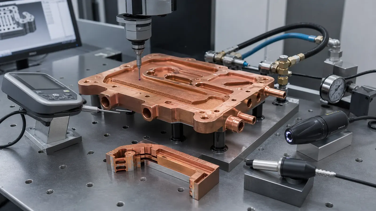
Figure 3. Dimensional accuracy for copper AM is accepted through a route: metrology, surface checks, leak or flow tests, and material evidence where needed.
Flatness, Size, and Position Are Different Requirements
A plus/minus dimension controls limits around a nominal size or coordinate; it is not a flatness callout. For example, writing “flatness +/-0.05 mm” leaves the form requirement confused. Specify flatness using the applicable geometrical tolerancing convention and identify the controlled surface. This is a notation example, not a proposed tolerance for a copper part.
For an ordinary surface-flatness requirement, the tolerance concerns form without a datum reference. A face’s orientation or location relative to other features needs the appropriate separate control. A compliant contact face can also behave differently free and clamped, so the agreed measurement and assembly conditions must be visible.
ISO 1101 defines the language and interpretation of geometrical specifications. Its public scope is not a supplier capability certificate; the responsible drawing authority must choose the applicable standard and complete callouts. Do not mix ISO and ASME conventions without review.
Build a Feature-Level Acceptance Record
The following is an illustrative record structure, not a completed inspection report. It connects a requirement to a result without assuming a universal tolerance or guaranteed machine capability.
| Record field | What the buyer and supplier should agree |
|---|---|
| Identity | Part, revision, serial/lot, and drawing feature identifier |
| Requirement | Characteristic, units, limit, controlled surface extent, datum reference where applicable, and drawing convention |
| Delivered state | Thermal processing, support removal, machining, plating and cleaning state at measurement |
| Measurement setup | Instrument/method, access, fixture/restraint, temperature conditions and measurement coverage |
| Result and uncertainty | Actual result, relevant measurement uncertainty and the agreed conformity decision rule |
| Disposition | Accepted, rejected or unresolved under that rule; approved deviation or rework and reinspection references if applicable |
ISO 14253-1 addresses conformity decisions that account for measurement uncertainty, including results near specification limits. For an RFQ, the practical action is to agree the rule before inspection, not argue from the instrument’s displayed decimal places after delivery. The table is a handover aid, not a reproduction of the standard’s procedures.
If two laboratories disagree, first reconcile part identity, delivered state, datum alignment, restraint, surface sampling and uncertainty. Do not average incompatible results or loosen the drawing simply to close the report. Record the unresolved condition and have the responsible parties agree the next measurement or disposition.
The existing datum and inspection-feature guide covers how to design the reference system; the channel-to-port stack guide covers remaining-wall and cross-process risks. This page covers how to specify and accept the finished feature.
Application-Specific Tolerance Priorities
Different copper AM applications spend tolerance in different places.
| Application | Highest-value tolerance controls |
|---|---|
| Cold plates and cooling blocks | Flat thermal faces, O-ring lands, threaded ports, pressure boundary, internal channel evidence |
| Compact heat exchangers | Port alignment, wall thickness, channel continuity, flow and pressure-drop validation |
| Semiconductor thermal parts | Datums, seal faces, clean interfaces, leak testing, CMM records, packaging and handling notes |
| RF and vacuum copper parts | RF mating surfaces, flange geometry, surface finish, plating route, leak and cleaning evidence |
| Busbars and cooled conductors | Contact-pad flatness, hole position, insulation clearance, plating, conductivity checks |
| Mold cooling inserts | Cavity-side machining stock, mounting datums, pressure-tested cooling channels, tooling interfaces |
| Heat sinks | Interface flatness, fin acceptance, damaged-feature criteria, thermal test setup |
For application pages, start with Copper cold plate RFQ page, Copper heat sink RFQ page, Copper AM Conformal Cooling Mold Inserts, or the Copper Cooling Block Design Review for Semiconductor Wafer Equipment.
RFQ Checklist For Copper AM Tolerances
Before asking for a copper metal 3D printing quote, prepare this tolerance package:
| RFQ item | What to provide |
|---|---|
| CAD model | STEP or native CAD with internal channels included |
| Drawing | Datums, critical dimensions, tolerances, reference dimensions, finish notes |
| Development stage | Concept, prototype, first article, pilot, or production |
| Material route | Pure copper, CuCrZr, CuCr1Zr, or supplier review |
| Machining scope | Faces, holes, ports, contact pads, seal lands, RF surfaces |
| Flatness and roughness | Contact faces, seal lands, thermal interfaces, RF paths |
| Seal and pressure data | O-ring, gasket, thread, fitting, working pressure, proof pressure, leak target |
| Internal channel evidence | Section views, cleaning access, CT, flow, pressure drop, coupon plan |
| Inspection package | CMM, roughness, CT, leak, pressure, flow, conductivity, hardness, first article report |
| Quantity and timing | Prototype, small batch, repeat build, qualification, target lead time |
For a broader quotation package, use Engineering Checklist for Copper 3D Printed Part Quotation. If drawings are not ready, the RFQ page explains what to send first.
FAQ
What tolerance can copper metal 3D printing hold?
There is no single reliable answer. As-built LPBF geometry is usually broader than machined copper features, while post-machined datums, holes, seal faces, and contact pads can be controlled tighter when they are accessible and properly fixtured. A useful RFQ separates as-built, machined, and functionally tested dimensions.
Can 3D printed copper parts hold +/-0.05 mm?
That cannot be promised from the material or process name alone. Send the feature, size, material state, machining access and inspection requirement for review. A bilateral size tolerance, a position tolerance and flatness are not interchangeable, even when a similar number appears in the callout.
Should threaded ports be printed directly?
For functional ports, printing the thread directly is usually not the preferred route. A stronger approach is to print a robust boss with enough wall thickness, then drill, tap, or machine the thread after printing. The drawing should define fitting type, thread standard, sealing method, and pressure requirement.
How should internal channel accuracy be specified?
Define minimum passage size, longest channel path, wall thickness, cleaning access, flow requirement, pressure drop, leak requirement, and inspection route. For hidden channels, CT, flow testing, pressure testing, or witness coupons may be more useful than a tight local dimensional tolerance that cannot be verified economically.
Does tighter tolerance always mean better copper AM performance?
No. Tighter tolerance improves performance only when it controls a real interface or risk. Over-tight tolerances on noncritical surfaces add cost and review time without improving thermal, electrical, RF, or fluid function. Spend tolerance on datums, contact faces, seals, ports, and assembly features.
Practical Next Step
Dimensional accuracy in copper metal 3D printing is a route decision.
Use copper AM where geometry creates value: internal channels, integrated manifolds, compact thermal structures, RF/vacuum shapes, high-current conductors, and low-volume functional hardware. Use machining where the part needs a controlled interface. Use inspection where the drawing needs proof.
The best copper AM tolerance package does not ask every feature to be perfect. It tells the supplier what must be printed, what must be finished, what must be measured, and what must be tested.
Send CAD, drawings, quantity, material preference, tolerance requirements, and acceptance scope to info@szcomo.com. If the tolerance strategy is uncertain, send the current drawing anyway and mark the critical interfaces. A targeted review is faster than forcing a global tolerance note that hides the real manufacturing work.
Copper AM quotation
Is copper AM a fit for your part?
Describe the part, its job, and the question holding up your decision. Add quantity and critical requirements if known; CAD can follow.
NDA available on request. We reply within 2 business days.
Before you submit: Copper AM capabilities and review scope.
