
Copper AM Conformal Cooling Mold Inserts
RFQ guide for copper additive manufacturing mold inserts: conformal cooling channels, CuCrZr selection, sealing faces, pressure testing, machining allowance, and acceptance inputs.
Working on a copper part? Start a project review — share a brief; CAD can follow.
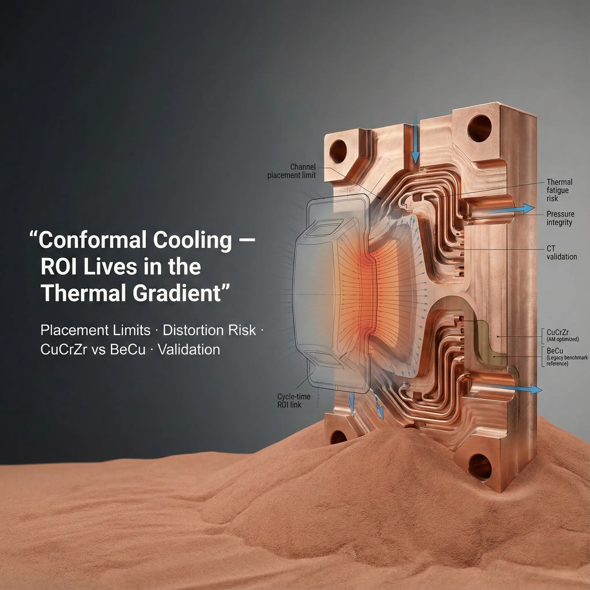
Copper AM mold inserts are worth reviewing when cooling path geometry, local heat extraction, cycle time, or part quality cannot be solved with straight drilled channels alone. Send the mold layout, insert CAD, channel design, pressure requirement, material target, machining stock, and acceptance tests before treating additive manufacturing as the chosen route.
Why Mold Inserts Are Different From Simple Cold Plates
A mold insert is not only a thermal part. It is also a precision tooling component with shutoff surfaces, cavity features, ejector logic, polishing requirements, and local wear risk. A conformal cooling idea may look good in a thermal model, but the RFQ still has to answer manufacturing questions.
The useful first question is:
Which molding problem is the cooling geometry meant to solve?
The answer may be cycle time, hot spots, warpage, sink marks, local crystallinity, short shots, tool temperature stability, or difficult heat removal around ribs, cores, pins, or deep pockets.
When Copper AM May Be Worth Reviewing
Copper additive manufacturing can be useful when the insert needs copper-level thermal conductivity and a channel path that conventional drilling cannot place close enough to the heat source.
Good review candidates include:
- Small or medium inserts where local cooling is more important than lowest insert cost.
- Core pins, slider inserts, or cavity details with concentrated heat load.
- Tooling that needs a cooling channel to follow a curved cavity wall.
- Inserts where straight drilled channels leave dead zones or long heat paths.
- Prototype tooling where the team needs to compare thermal response quickly.
- CuCrZr or copper alloy inserts where strength and conductivity must be balanced.
Weak candidates are simple plates, large blocks with straight drilling access, cosmetic inserts where thermal performance is not the limiting factor, or inserts where the printed channel cannot be cleaned, sealed, or pressure tested.
RFQ Inputs That Change Feasibility
A mold insert RFQ should not start from the printed geometry alone. The supplier needs to understand both the cooling function and the tooling interfaces.
| Input | Why it matters |
|---|---|
| Mold assembly context | Shows shutoff surfaces, cavity side, core side, ejector pins, screws, and keep-out zones |
| Insert CAD and drawing | Defines datums, machining stock, tolerances, polish faces, threads, and sealing areas |
| Cooling channel model | Confirms diameter, bend radius, distance to cavity wall, branches, and cleaning access |
| Coolant and pressure | Drives leak test, proof pressure, wall thickness, and port design |
| Material target | Pure copper, CuCrZr, or another copper alloy changes strength, heat treatment, and cost |
| Surface requirements | Printed surfaces, machined faces, cavity finish, and polishing scope are different costs |
| Quantity and lead time | Prototype insert, pilot tool, and production tool need different inspection depth |
| Acceptance tests | Pressure, flow, leak, CMM, hardness, conductivity, or thermal trial expectations |
If the RFQ only includes an STL or a concept image, the response will need assumptions. A STEP model, 2D drawing, channel sketch, and operating pressure make the quote more useful.
Channel Design: Do Not Optimize Only For Distance
The channel should be close enough to remove heat, but not so aggressive that it creates tooling risk. For copper AM mold inserts, the channel review usually asks:
- What is the minimum wall thickness between channel and cavity face?
- Can powder be removed from every branch and bend?
- Are there blind ends or trapped pockets?
- Are ports, plugs, and O-ring regions accessible for machining?
- Is the bend radius printable and cleanable?
- Does the channel pass near threaded holes, ejector pins, or thin ribs?
- Can the finished insert be pressure tested without special fixtures?
The best channel is not the most complex channel. It is the channel that solves the thermal problem while staying cleanable, inspectable, and tool-safe.
Material: Pure Copper Or CuCrZr?
Pure copper may be reviewed when thermal conductivity is the primary requirement and mechanical load is moderate. CuCrZr may be reviewed when strength, thread stability, clamp load, service temperature, or repeated tool cycling matters.
The RFQ should state which property is more important:
- Maximum thermal conductivity.
- Higher strength and hardness.
- Machined cavity detail stability.
- Thread or bolt-load durability.
- Polishing and finishing behavior.
- Heat treatment and conductivity target.
The EOS CuCrZr process sheet for its M 290 1 kW, 80 micrometre route reports material properties by manufacturing and heat-treated state. It supports asking for route-specific evidence, not assuming another machine or mold insert has the same properties.
Do not select an alloy only from a generic conductivity table. The insert has to survive machining, installation, pressure, thermal cycling, and production handling.
Use the materials page when alloy choice is still open, and use the process selection guide when the insert may also be drilled, brazed, or assembled.
When the insert decision is mainly about thread strength, pressure boundaries, clamp load, thin walls near conformal channels, or heat-treated evidence, use CuCrZr 3D Printing: When Strength Matters More Than Maximum Conductivity as the material route gate before comparing mold cooling performance.
Post-Machining Is Usually Part Of The Route
Most copper AM mold inserts are not used as-printed. The quote may include additive manufacturing plus CNC machining, EDM, polishing, thread machining, O-ring groove machining, pressure testing, and cleaning.
State which surfaces must be controlled:
- Cavity surface and polish requirement.
- Shutoff faces and parting-line regions.
- Mounting datums and clamp faces.
- Port threads, plugs, fittings, and sealing lands.
- Ejector, screw, and alignment holes.
- Faces that need CMM inspection.
If a cavity surface needs a high cosmetic finish, that surface should not be treated like an internal printed channel. The drawing should separate functional surfaces from non-critical printed surfaces.
Pressure, Leak, Flow, And Cleaning
Conformal cooling channels only help if they can be accepted after printing and machining. A practical RFQ defines:
- Working pressure and proof pressure.
- Coolant type and temperature range.
- Leak test method or acceptance expectation.
- Flow direction and target flow rate if known.
- Cleaning route, flushing access, and drying requirement.
- Whether CT review, sectioned sample, or pressure report is needed.
Agree the prototype acceptance package against the actual risk. Proof pressure, leak testing and flow measurements answer different questions; a prototype label does not make any required check unnecessary. Production tooling also needs the specified life, surface and traceability evidence.
When Conventional Tooling May Be Better
Copper AM may not be the best first route when:
- Straight drilled channels already reach the heat source.
- Cooling is not the main constraint in the molding process.
- The insert is large and simple enough for conventional machining.
- Internal channel cleaning cannot be verified.
- The required cavity finish removes too much printed stock.
- The design has no pressure, coolant, or acceptance information.
These points should be addressed before the RFQ becomes a price comparison. Additive manufacturing should be selected because it changes the cooling result, not because it sounds advanced.
Related Tooling and Validation Guides
For a deeper mold example, review the CuCrZr cooling insert design review for injection mold hot spots. If the insert is likely to use CuCrZr, pair the RFQ with the CuCrZr heat treatment guide so hardness, conductivity, and aging condition are not left implicit.
Conformal cooling inserts also depend on powder removal for copper AM internal channels, tolerances and dimensional accuracy, and post-processing methods for 3D printed copper parts. These guides help separate printed cooling geometry from the machined tooling surfaces that control the mold.
Practical RFQ Checklist
Send:
- Insert STEP file and 2D drawing.
- Mold assembly context or screenshots showing functional interfaces.
- Cooling channel model or sketch.
- Material preference and whether equivalent review is allowed.
- Coolant, pressure, flow, and temperature expectations.
- Machining stock and critical surfaces.
- Cavity finish, polish, coating, or plating requirement.
- Quantity, timing, and prototype or production intent.
- Pressure, leak, flow, CMM, hardness, conductivity, or CT inspection needs.
Send files to info@szcomo.com. If the channel concept is not final, send the current model and the molding problem it is meant to solve. The review can then compare additive manufacturing with conventional machining, drilling, brazing, or redesign.
Copper AM quotation
Review a copper cooling insert
Share the tooling hot spot, insert envelope, and available coolant conditions. Add cavity interfaces, wear requirements, and CAD if available.
NDA available on request. We reply within 2 business days.
Before you submit: Copper conformal cooling insert service.
