
3D Printed Copper Heat Sinks: Feasibility Guide
Decide whether a copper heat sink should be 3D printed, then compare a replacement in the installed assembly with controlled interfaces, fan settings and acceptance evidence.
Working on a copper part? Start a project review — share a brief; CAD can follow.
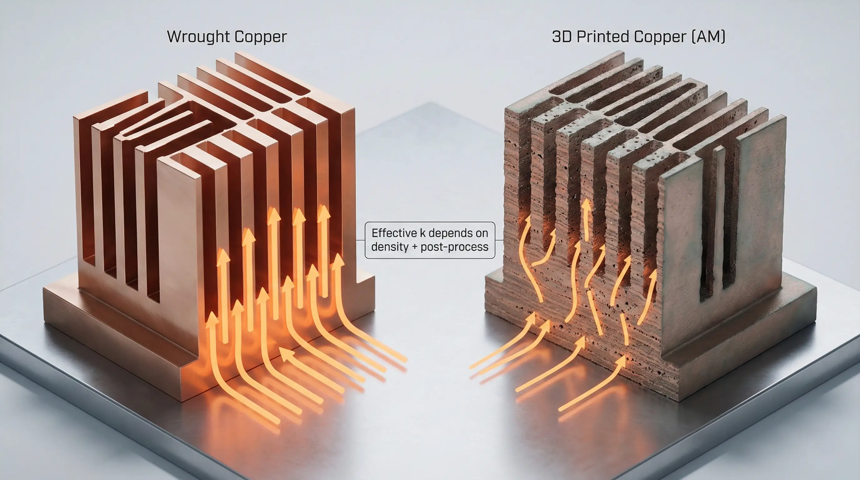
Yes, copper heat sinks can be 3D printed. The route makes engineering and commercial sense only when additive geometry creates enough value to justify copper powder-bed processing, support removal, heat treatment, machining, cleaning, inspection, and validation.
Good candidates need internal flow paths, non-straight fins or pins, compact ducting, integrated manifolds, part consolidation, or a geometry that cannot be made efficiently by skiving, machining, extrusion, forming, or brazing. A simple copper base with straight fins is usually a conventional-manufacturing job.
Use the 3D printed copper heat sink RFQ page when drawings are ready. This guide explains the feasibility decision before quotation.
Quick go/no-go screen
| Project condition | Feasibility signal |
|---|---|
| Straight fins on a flat base | Usually keep skiving, machining, bonding, or brazing |
| Internal liquid passages or integrated manifold | Strong reason to review copper AM |
| Curved, branching, or spatially varying fin field | AM may create useful airflow or packaging value |
| Very thin features with no depowdering or support plan | High redesign risk |
| Critical contact face can be machined | Feasibility improves |
| Performance depends on as-built textbook copper conductivity | Weak assumption; require qualified material data |
| Thermal test condition is defined | Quote and comparison become more meaningful |
| Only objective is lower unit price | AM is usually a weak fit |
What type of heat sink is being requested?
The term “heat sink” covers several different manufacturing problems:
- an air-cooled fin or pin structure;
- a liquid-cooled heat sink with internal passages;
- a cold plate with an external fin field;
- a manifold that distributes coolant to several thermal zones;
- an RF, laser, power-electronics, or semiconductor component that also acts as a heat sink;
- a high-current copper part that combines conduction and cooling.
These parts should not share one generic design rule. Air-cooled hardware is controlled by fin geometry, airflow, interface resistance, and handling. Liquid-cooled hardware adds channel roughness, pressure drop, powder removal, cleaning, pressure integrity, and leak testing. RF and semiconductor parts add surface, cleanliness, vacuum, and documentation requirements.
Define the actual function before selecting a print process.
Where copper AM can outperform conventional fabrication
Internal cooling near the heat source
LPBF can place curved or distributed channels inside a copper body and connect them to integrated headers or ports. This is useful when straight drilling cannot reach the thermal zone or when a brazed cover would add a joint in a pressure boundary.
The benefit is not “more channels” by itself. A useful design balances local heat transfer with pressure drop, powder exit, flushing access, wall thickness, and inspection. Review the internal-channel cleaning guide before making passages smaller.
Non-straight fins, pins, and airflow paths
AM can vary fin direction, thickness, height, or density across the part. It can also create compact pin fields or features aligned to a constrained flow path. This is valuable when the available air stream is not compatible with a conventional straight-fin layout.
More surface area is not automatically better. If spacing is too tight, the part may trap powder, require supports, starve airflow, or become difficult to inspect and clean. The heat-sink fin thickness and spacing guide addresses this geometry gate.
Part consolidation
A printed heat sink may combine the base, channels, manifold, mounting bosses, sensor ports, and duct features. Consolidation can remove joints and assembly steps, but it also concentrates risk in one component. Critical faces and ports still need machining access, and a rejected late-stage part carries all previous processing cost.
Low-volume geometry iteration
AM can be useful for prototypes and low-volume systems when the internal geometry is expected to change. The economic comparison should include the complete accepted component, fixture and tooling cost, engineering iteration, and the value of avoiding a complex brazed or machined assembly.
Where conventional heat-sink manufacturing remains stronger
Keep conventional manufacturing when the part can be produced as:
- a machined copper base with drilled features;
- a skived, bonded, stamped, or brazed straight-fin heat sink;
- an extruded aluminum or copper profile with secondary machining;
- a simple water block with accessible channels and a joined cover;
- a high-volume design already supported by stable tooling and tests.
Conventional processes often provide better economics, known surface condition, easier inspection, and simpler finishing for these geometries. Copper AM should solve a geometry or integration problem, not replace a mature process without a measurable reason.
Material route: pure copper or CuCrZr
Pure copper is usually reviewed when heat spreading or electrical conductivity is the primary requirement. CuCrZr is often reviewed when thin features, threads, pressure boundaries, clamp load, handling, or thermal exposure require more mechanical stability.
Do not compare only nominal conductivity. Ask for the proposed material state, heat treatment, density or property evidence, build orientation, and finished-part test scope. Then evaluate whether interface resistance, coolant or airflow, and geometry dominate the system result.
Use Pure Copper vs CuCrZr Heat Sinks for the material decision and Copper AM Materials for the broader alloy route.
Geometry gates for a printed copper heat sink
Fins and pins
Minimum feature size depends on process, material, orientation, aspect ratio, support strategy, and handling. A supplier capability statement should distinguish a one-off coupon from a repeatable production feature on the actual part. Include inspection and allowed cosmetic or dimensional variation.
Internal channels
Channel shape and size affect print stability, support need, roughness, powder removal, pressure drop, and CT visibility. Provide at least two independent openings where practical and avoid blind retention zones. Design ports for flushing and test-fixture connection, not only final assembly.
Thermal interface
The device contact face normally needs final machining or grinding. State flatness, roughness, parallelism, datum relationship, coating, TIM, and clamp approach. A high-conductivity body cannot compensate for a poor interface.
Mounting and ports
Threads, O-ring grooves, sealing lands, holes, and datum features should have machining stock and tool access. Define working pressure, proof pressure, leak method, and torque requirements when the heat sink carries fluid or repeated assembly loads.
The full manufacturing route
A realistic quote may include:
- DfAM and build-orientation review.
- Material and process selection.
- Printing with witness coupons where required.
- Stress relief or alloy heat treatment.
- Separation and support removal.
- Internal depowdering, flushing, and drying.
- CNC machining of interfaces, ports, seals, and datums.
- Surface finishing or plating where required.
- Dimensional, material, flow, pressure, leak, and thermal acceptance.
The print is only one step. The cost and schedule should be compared at the accepted-component level.
How to verify thermal performance
A useful test definition includes the heat-source footprint and power, interface material and bond-line control, clamp method, inlet air or coolant temperature, airflow or flow rate, pressure drop, ambient condition, sensor locations, stabilization criterion, and reported uncertainty.
For air-cooled parts, specify the fan or blower operating point rather than a free-air flow value. For liquid-cooled parts, record flow and pressure drop at the tested condition. If two manufacturing routes are compared, use the same interface and boundary conditions.
Dimensional acceptance alone does not prove thermal performance. CT does not prove cleanliness, flow, leakage, or heat transfer. Select tests according to the failure modes that matter.
RFQ checklist
For a new part, use the inputs below. For an existing part that misses its temperature target, first preserve the baseline and use the replacement comparison that follows.
Send:
- STEP file and controlled drawing.
- Heat source, footprint, heat load, and temperature target.
- Airflow or coolant, flow rate, inlet temperature, and pressure-drop limit.
- Working and proof pressure plus leak target for fluid parts.
- Contact face, flatness, roughness, TIM, and clamp details.
- Material preference and accepted alternatives.
- Machining, coating, cleaning, and packaging requirements.
- Dimensional, CT, flow, leak, pressure, conductivity, or thermal tests.
- Prototype and expected production quantities.
- Target timing and any qualification milestones.
Compare a replacement in the installed assembly
A replacement study asks a narrower question than “can this heat sink be printed?”: can the proposed finished part meet the requirement inside the allowed assembly, without transferring the problem to the fan, interface, noise limit or maintenance route?
Use two distinct comparisons. A controlled-flow bench comparison can isolate how two heat sinks behave at a specified airflow. An installed-system comparison keeps the agreed enclosure and fan control conditions, then measures the operating result. Do not present one as the other.
The fan operating point follows the intersection of its performance curve and the system resistance curve, as explained in ebm-papst’s fan engineering FAQ. Changing the fin field can change that intersection. The same fan, speed setting or free-air rating does not prove that equal air passes through both parts.
Use a comparison record such as this before ordering the first printed replacement:
| Record item | Hold fixed or explicitly account for | What would invalidate the comparison? |
|---|---|---|
| Source and duty | Heat input, footprint, load distribution and steady or transient duty | One concept is tested at a lower load or a different heat-source location |
| Installed airflow | Enclosure, ducting, bypass gaps, inlet temperature, fan model and control setting | A free-air rating is substituted for the installed condition, or the enclosure changes without being reported |
| Contact stack | TIM, application method, contact faces, clamp procedure and mounting orientation | An interface improvement is attributed solely to the printed fin geometry |
| Temperature result | Named measurement points, limits, sensor method and stabilization rule | A base temperature is compared with a component or junction temperature |
| Confidence in the difference | Measurement uncertainty and a repeat mounting/test check where assembly variation matters | The claimed gain cannot be distinguished from measurement or setup variation |
| Purchased scope | Finished material state, machining, coating, inspection, quantity and included testing | A printed blank is compared with a finished, accepted conventional part |
This is a proposed review template, not a customer result or a universal test specification. Natural-convection parts need the relevant orientation, ambient and surrounding-clearance conditions instead of a forced-air fan comparison. Liquid-cooled designs need the corresponding fluid, flow and hydraulic boundaries.
Decide whether to build, revise or keep the baseline
- Proceed to a scoped prototype: the candidate addresses a named constraint, the comparison is reproducible, and the geometry can be manufactured and inspected. This is permission to learn from a build, not approval for a production batch.
- Revise the test or interface first: the apparent gain depends on a changed TIM, clamp, inlet condition or enclosure. Keep those changes visible and assess whether the current heat sink can meet the requirement with them.
- Retain the conventional part: it meets the agreed duty and the printed candidate does not show sufficient functional or packaging value to justify its total delivered cost and qualification effort.
When a simulation and bench test disagree, use the thermal model-to-test decision record before accepting or discarding the design. For a purchasing discussion, send the baseline result, the missed limit, allowed changes and prototype quantity through the custom heat sink review path. Missing CAD can remain an open item; do not invent boundary conditions to obtain a nominal price.
Frequently asked questions
Are 3D printed copper heat sinks better than machined heat sinks?
Only when the geometry or integration advantage outweighs the added print and post-processing route. Machining is normally better for simple accessible shapes. AM is stronger for non-line-of-sight geometry, internal channels, consolidation, and low-volume complexity.
Can a printed heat sink use its as-built base as the device interface?
That is rarely the preferred route for a high-performance interface. Contact faces normally need controlled machining or grinding, followed by flatness and roughness inspection.
Does a denser fin field always cool better?
No. Dense fins can increase surface area while reducing airflow, increasing pressure drop, trapping powder, or becoming too fragile to clean and handle. Evaluate the complete flow system.
Is CT required for every printed copper heat sink?
No. CT is useful when internal geometry or hidden defects justify it, especially during first-article review. Flow, pressure, leak, dimensional, and thermal tests may provide more direct evidence for other requirements.
Technical context
- Laser 3D printing of complex copper structures discusses laser processing and complex copper heat-sink structures in the additive-manufacturing literature.
- Copper AM vs CNC machining compares manufacturing routes based on geometry and accepted-part requirements.
Send the CAD, quantity, thermal conditions, interfaces, and test requirements to info@szcomo.com for review.
Copper AM quotation
Review a copper heat sink design
Share the heat source, available envelope, and cooling conditions. Add an interface sketch, CAD, or quantity if available; a complete specification is not needed to start.
NDA available on request. We reply within 2 business days.
Before you submit: Custom copper heat sink service.
