
Pure Copper vs CuCrZr Heat Sinks
Choose pure copper or CuCrZr for a 3D printed heat sink by comparing conductivity, clamp stability, thin features, heat treatment, finishing, and acceptance requirements.
Working on a copper part? Start a project review — share a brief; CAD can follow.
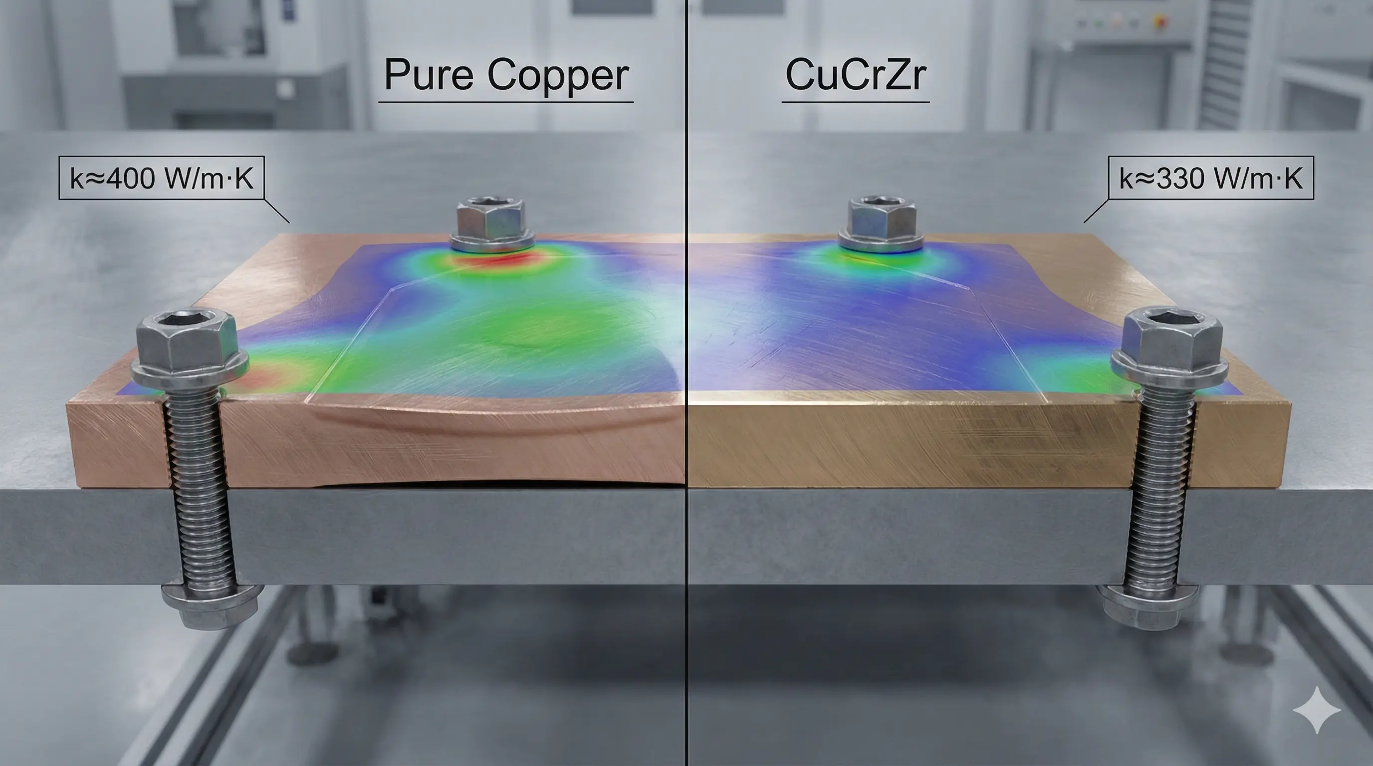
Pure copper is usually the first material to review when a heat sink is limited by heat spreading or electrical conductivity. CuCrZr is often the safer route when the same part must also hold threads, thin fins, pressure boundaries, clamped interfaces, or dimensional stability through manufacturing and service.
The correct choice is not the alloy with the best single data-sheet value. It is the material and post-processing route that produces the lowest thermal resistance after printing, heat treatment, machining, assembly, and testing.
EOS describes pure copper for conductivity-driven applications and CuCrZr as a heat-treated route balancing conductivity with mechanical properties. The drawing still needs project-specific property and acceptance requirements because supplier data is process- and condition-dependent.
For a commercial project, start with the 3D printed copper heat sink RFQ page and use this guide to decide which material states should remain open in the quotation.
Quick material decision
| Dominant requirement | Material to review first | Why |
|---|---|---|
| Maximum heat spreading with low mechanical load | Pure copper | Prioritizes thermal and electrical conductivity |
| Thin fins, pins, bosses, or threaded features | CuCrZr | Adds strength and handling stability |
| Tight interface flatness under clamp load | CuCrZr or a structurally supported pure-copper design | Base distortion can increase thermal interface resistance |
| Internal liquid channels with pressure and ports | CuCrZr often deserves review | Pressure boundaries and machined ports add mechanical requirements |
| High-current thermal hardware | Pure copper first, then compare CuCrZr | Current path, contact pads, temperature, and structure must be evaluated together |
| Elevated-temperature or repeated thermal exposure | CuCrZr with a controlled heat-treatment route | Finished properties depend on the complete thermal history |
This table is a route-selection starting point. The actual decision still depends on the qualified material data, part geometry, heat-treatment state, and acceptance plan.
Why the highest conductivity does not always produce the best heat sink
A heat sink is a thermal system, not a material coupon. Its temperature rise can include:
- spreading resistance through the base;
- resistance across the device, TIM, coating, and mounting interface;
- conduction through fins, pins, walls, or internal structures;
- convection to air or coolant;
- flow maldistribution and pressure-drop losses;
- dimensional change that alters contact pressure or bond-line thickness.
Pure copper can improve the bulk-conduction part of that stack. It cannot correct a warped base, an excessive TIM layer, a blocked channel, weak airflow, or a poorly machined contact pad. A lower-conductivity CuCrZr body may perform more consistently if it preserves flatness and feature geometry under assembly load.
That is why the material review should happen after the thermal boundary conditions are defined. Send heat-source footprint, heat load, contact area, mounting method, airflow or coolant condition, and the acceptance test. Without those inputs, a conductivity comparison is incomplete.
What pure copper offers
Pure copper is attractive for high-heat-flux components because it can provide the highest thermal and electrical conductivity among the commonly requested copper AM routes. It is a strong candidate for:
- heat spreaders and bases where bulk conduction dominates;
- compact air-cooled structures with limited mechanical loading;
- conductive thermal parts that also carry current;
- cold plates where thermal performance has priority and the geometry can support the pressure and interface requirements;
- RF or high-current hardware where surface and bulk conductivity both matter.
The engineering trade-off is mechanical reserve. Printed and heat-treated pure copper may require thicker load paths, separate inserts, supported threads, conservative handling, or a stiff backing structure. Critical faces normally need machining after the build and any required thermal processing.
The RFQ should not assume that wrought-copper handbook values automatically describe the printed part. Ask which property data applies to the proposed machine, powder, build orientation, heat treatment, and test method. The electrical conductivity guide explains the difference between material data, witness coupons, contact resistance, and finished-component evidence.
What CuCrZr offers
CuCrZr is a precipitation-hardening copper alloy. Compared with pure copper, it generally sacrifices some conductivity to gain strength, feature stability, and better resistance to mechanical damage. It is often worth reviewing when the heat sink includes:
- thin fins or pins that must survive depowdering, cleaning, machining, handling, and assembly;
- threaded ports, bosses, fastener features, or repeated torque cycles;
- pressure boundaries or internal liquid channels;
- a thin base under meaningful clamp load;
- sealing lands, O-ring grooves, or precision datums;
- service or manufacturing temperatures that make pure-copper softening a concern.
CuCrZr only provides this benefit when the heat-treatment state is controlled. Solution treatment, aging, stress relief, brazing, soldering, coating, and later thermal exposure can interact. The drawing and purchase requirement should state the required condition and evidence rather than requesting “CuCrZr” with no finished-property definition.
Use the CuCrZr heat-treatment guide when hardness, conductivity, strength, or coupon evidence must be included in the quote.
Five design checks that decide the material route
1. Is the thermal bottleneck in the copper body?
If simulation or test shows that base spreading dominates, pure copper may provide a meaningful advantage. If the largest resistance sits at the TIM, contact face, airflow, or coolant boundary, changing alloy may have less impact than improving the interface or geometry.
2. What loads act on the finished heat sink?
Define clamp force, bolt torque, thread engagement, unsupported span, pressure, vibration, shock, and handling. A heat sink that also acts as a manifold or structural mount needs more than a conductivity target.
3. Which features remain as-built?
Thin fins, lattice surfaces, internal channels, and inaccessible regions inherit the qualified AM surface and dimensional capability. Contact faces, holes, ports, seal lands, and datums should normally be separated into a machining and inspection plan.
4. What thermal history follows printing?
Heat treatment, stress relief, HIP where applicable, brazing, soldering, plating bake, and service temperature can change material state and distortion. Sequence these steps before final machining and acceptance testing.
5. What evidence accepts the part?
Useful evidence may include material certificates, witness-coupon density, conductivity, hardness, CMM inspection, flatness, roughness, flow, pressure, leak, and functional thermal testing. Select the evidence that controls the real failure risk.
Do not compare materials without comparing manufacturing routes
Material selection and process selection are linked. A pure-copper printed body with heavy machining may compete against a machined or skived copper heat sink. A CuCrZr printed manifold with integrated cooling may compete against a brazed multi-piece assembly. The quote should compare accepted finished components, not printed blanks.
Keep a conventional route when the heat sink is a simple base with straight fins, drilled holes, or an accessible channel network. Consider AM when the design needs internal flow paths, non-line-of-sight geometry, part consolidation, variable fins, or compact routing that cannot be manufactured cleanly by cutting, skiving, extrusion, or brazing.
The 3D printed copper heat sink feasibility guide covers that route decision in more detail.
RFQ inputs for a defensible material comparison
Send these inputs before asking a supplier to choose pure copper or CuCrZr:
- STEP file and controlled drawing.
- Heat-source location, footprint, and heat load.
- Maximum component or interface temperature.
- Airflow, coolant, flow rate, pressure drop, and pressure requirements.
- Clamp load, fasteners, torque, threads, and structural loads.
- Critical flatness, roughness, thickness, and machined surfaces.
- Material condition, heat treatment, and accepted equivalents.
- Required conductivity, hardness, dimensional, leak, flow, or thermal tests.
- Prototype, qualification, and production quantities.
Do not specify a tight value for every property by default. Each added acceptance requirement changes coupons, test methods, sampling, cost, and lead time. Define the properties that control the application.
Frequently asked questions
Is pure copper always better for a heat sink?
No. Pure copper usually offers higher conductivity, but system performance can be limited by interface resistance, geometry, airflow or coolant, flatness, and mechanical stability. The finished assembly decides the result.
Is CuCrZr strong enough to replace structural material?
That cannot be assumed from the alloy name. Strength depends on composition, build route, orientation, heat treatment, geometry, temperature, and acceptance evidence. Treat it as a copper alloy with useful mechanical reserve, not as a universal structural substitute.
Can pure copper and CuCrZr be quoted as alternatives?
Yes, when the drawing states the critical thermal, mechanical, and inspection requirements instead of locking an alloy without explaining why. An alternative quote can compare material availability, process risk, post-processing, and evidence.
Which material is better for a liquid-cooled heat sink?
Pure copper may favor heat spreading. CuCrZr may favor pressure boundaries, ports, thin walls, and assembly stability. The decision depends on channel geometry, working and proof pressure, sealing, machining, and the thermal target.
Technical context
- EOS copper materials for industrial 3D printing describes pure-copper and copper-alloy application directions and material-specific routes.
- Copper alloy selection for metal 3D printing compares pure Cu, CuCrZr, and CuCr1Zr across a broader range of components.
For a quote, send the drawing, quantity, thermal conditions, interface requirements, and required evidence to info@szcomo.com.
Copper AM quotation
Review a copper heat sink design
Share the heat source, available envelope, and cooling conditions. Add an interface sketch, CAD, or quantity if available; a complete specification is not needed to start.
NDA available on request. We reply within 2 business days.
Before you submit: Custom copper heat sink service.
