
Common Design Mistakes in 3D Printed Copper Parts
Review copper AM design mistakes and the risks a correction can introduce: channels versus walls, machining stock versus final geometry, material changes, and acceptance gaps.
Working on a copper part? Start a project review — share a brief; CAD can follow.
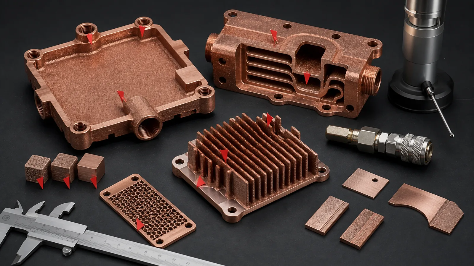
Review the finished manufacturing route before locking a 3D printed copper design. Thin walls near ports, hidden powder traps, missing machining stock, unsupported fins, undefined material state, and unclear acceptance tests can leave a printable shape unsuitable for its intended service. A correction should close the original problem without creating an unreviewed risk elsewhere.
The first mistake is thinking that a printable copper shape is the same thing as a usable copper component.
A cold plate, manifold, heat sink, RF cavity, or conductor can look convincing in CAD while the manufacturing route remains incomplete. A successful export does not establish that a channel can be cleaned, a port can be finished without breaking into a passage, or a thermal face can meet the drawing after machining.
These are design-review risks, not reports of completed customer projects. Dimensions, pressure ratings, machining stock, and inspection limits must come from the actual geometry, material state, process route, and acceptance requirements, not from an illustrative rendering.
Copper additive manufacturing is valuable because copper can carry heat, current, RF energy, and fluid paths through compact geometry. That same value creates stricter design discipline. Copper conducts heat away from the melt zone quickly, reflects common laser energy, and often needs finished surfaces after printing. A good design should account for the route from CAD to accepted part: print, depowder, heat treat if required, machine critical faces, clean, inspect, and test.
Mistake 1: Copying Generic Metal AM Rules Into Copper
Copper is not stainless steel with a different color.
General laser powder bed fusion rules can help at the concept stage, but they do not qualify a particular copper route. NIST research on LPBF of highly reflective metals discusses the energy-coupling challenge for reflective metals such as copper and aluminum. Confirm geometry limits with evidence for the proposed alloy, machine, parameters, orientation, and post-processing rather than importing another material’s design rules.
The mistake usually appears as a stainless-steel AM habit transferred directly into copper:
- Thin unsupported walls without a build-orientation review.
- Long overhangs that assume support scars do not matter.
- Dense lattice or fin fields that ignore cleaning and inspection.
- Internal channels designed only from CFD pressure-drop targets.
- Tight blanket tolerances applied to every surface.
- No material route decision between pure Cu, CuCrZr, and CuCr1Zr.
The correction is simple but not always convenient: design copper AM as a finished manufacturing route, not only as a geometry process. If the part carries heat, pressure, current, RF energy, or vacuum service, the CAD model should show how the part can be printed, cleaned, finished, and verified.
For the design-rule foundation, start with Design Rules for Copper Laser Powder Bed Fusion Parts. For file preparation, use How to Prepare CAD Files for Copper Metal 3D Printing.
Mistake 2: Making Internal Channels Too Small to Clean
Internal channels are one of the strongest reasons to use copper 3D printing. They are also where many copper AM designs fail review.
A channel may look efficient in thermal simulation, but simulation does not remove powder. Sharp turns, blind pockets, a long enclosed path, or too few access openings can prevent effective powder removal. Increasing the nominal diameter alone does not establish cleanability when the path remains tortuous or inaccessible.
The common mistakes are:
- Designing the smallest channel that CFD allows.
- Creating dead-end pockets near manifolds.
- Placing inlet and outlet ports without a cleaning route.
- Ignoring the longest enclosed path between openings.
- Forgetting that rough internal LPBF surfaces raise pressure drop.
- Treating CT inspection as a substitute for cleanability.
A better design asks three questions before the quote:
- Can powder leave the channel after printing?
- Can the channel be flushed and dried?
- Can the finished part prove flow, pressure, or cleanliness?
The best channel is not always the smallest channel. A larger passage with direct access is a candidate when a dense microchannel network cannot be cleared. Treat a revised section or added cleaning access as a design change requiring thermal, hydraulic and closure review, not a universally safer dimension. Use the internal-channel DFM workflow to record the trade-off and verification plan.
For deeper planning, see Copper AM Cleaning and Powder Removal for Internal Channels and 3D Printed Copper Heat Exchangers: Design Benefits and Manufacturing Limits.
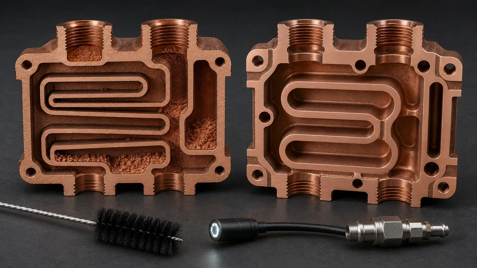
Figure 2. Illustrative channel-review arrangement, not a customer part or test result. Review the full path, dead-end volume, cleaning access, and required verification before locking the design.
Mistake 3: Forgetting Machining Stock on Critical Faces
A printed copper surface is not automatically a finished surface.
This is a frequent mistake on cold plates, heat sinks, RF parts, conductors, and tooling inserts. The model shows the final shape. The drawing asks for a finished function. But the CAD package does not leave material for machining.
Critical surfaces often need post-processing:
- Thermal contact faces.
- O-ring lands and seal grooves.
- Threaded ports.
- Electrical contact pads.
- RF mating surfaces.
- Vacuum sealing faces.
- Datum pads.
- Mounting faces.
Machining stock must be agreed for the part size, orientation, expected distortion, heat treatment, fixturing, and final tolerance. This guide does not assign a universal allowance. The error is omitting the finishing route or checking wall thickness only on the printed blank rather than on the finished component.
Missing stock creates a chain reaction. Adding stock later can reduce wall thickness near a channel, move a sealing land closer to a port, change support strategy, increase build height, or force a different datum scheme. That is why the printed blank and finished part should be separated early.
If the CAD model represents the finished part, tell the supplier which faces need machining allowance before printing. If the CAD model represents the printed blank, the drawing should define the final machined dimensions.
This also affects cost. A quote for a printed body is not the same as a quote for a finished accepted component. See Cost Drivers in Copper 3D Printing Projects for the full cost ledger.
Mistake 4: Weak Port Bosses and Threads
Ports are design features, not decoration.
In copper AM, a threaded port may need to carry pressure, torque, seal compression, repeated assembly, and cleaning access. It may also sit near an internal channel or thin wall. A port that looks clean in CAD can become a failure point after machining, especially if the thread depth, wall thickness, and sealing method are not reviewed together.
Common port mistakes include:
- Threaded ports too close to internal channels.
- Thin walls left after tapping or thread milling.
- No boss thickness around high-load fittings.
- O-ring or face-seal geometry treated as an afterthought.
- No torque or repeated assembly expectation.
- No working pressure or proof pressure in the RFQ.
An illustrative issue is a cooling block whose remaining wall near a port is inadequate after thread machining and channel clearance are considered. Required wall thickness depends on the actual geometry, material state and loading; this example assigns no safe pressure rating. A larger boss, shifted channel, different fitting or material review may be needed, followed by verification against the controlled requirements.
Pure copper can be appropriate when thermal or electrical conductivity dominates. CuCrZr or CuCr1Zr may deserve review when port strength, repeated tightening, clamp load, or pressure boundary integrity matters. For material trade-offs, see Copper Alloy Selection for Metal 3D Printing: Pure Cu vs CuCrZr vs CuCr1Zr and Pure Copper vs CuCrZr for 3D Printed Heat Transfer Parts.
Mistake 5: Over-Tight Tolerances Everywhere
Tolerance discipline is not the same as tolerance aggression.
A blanket +/-0.05 mm requirement across a complex copper AM body can turn a feasible prototype into an expensive machining and inspection project. Some features deserve tight control. Many surfaces do not.
Use tighter tolerance where the function requires it:
- Thermal contact face flatness.
- Seal groove dimensions.
- Port position and thread depth.
- Datum pads.
- Critical hole patterns.
- RF interface geometry.
- Electrical contact pads.
Relax or leave as-built where the function allows:
- Non-contact outer walls.
- Cosmetic surfaces.
- Internal flow surfaces where roughness is acceptable.
- Support-facing surfaces that are later hidden.
- Noncritical pockets and mass-reduction features.
This is consistent with the broader AM design logic in ISO/ASTM 52911-1:2019, which provides design guidance for laser-based powder bed fusion of metals. The standard is not a copper-specific tolerance table, but it supports the larger point: PBF-LB/M parts need process-aware design and specification, not generic drawing notes copied from machined parts.
A better drawing separates the part into zones: machined, inspected, as-built acceptable, support-sensitive, and noncritical. That lets the quote carry the real work instead of pricing every face as if it were a datum.
Mistake 6: Designing Unsupported Thin Fins or Fragile Lattice Without a Test Plan
Dense copper fins, pins, and lattice structures can be attractive in a rendering. They can also become fragile, costly, or underperforming if airflow, cleaning, supports, and finishing are not included.
The mistake is usually a thermal model that assumes ideal geometry:
- Very thin fins with no mechanical review.
- Tight spacing that is difficult to print or clean.
- Tall aspect ratios that raise distortion or handling risk.
- Airflow paths that clog or create high pressure drop.
- No plan for measuring real thermal performance.
- No acceptance criterion for damaged fins or local roughness.
For air-cooled heat sinks, smaller features do not automatically improve performance. If the flow cannot enter the fin field, or if interface flatness dominates the thermal resistance, the dense printed geometry may not deliver the expected result. For liquid-cooled parts, a dense micro-feature field may increase surface area while creating trapped powder and uncertain pressure drop.
If the design uses thin fins, pins, lattice, or turbulators, include the functional reason and test method. Thermal load, airflow or coolant flow, interface pressure, allowable pressure drop, and test fixture conditions matter more than a beautiful render.
For heat sink-specific issues, see 3D Printed Copper Heat Sinks for Power Electronics Cooling, Minimum Fin Thickness and Spacing for 3D Printed Copper Heat Sinks, and Thermal Performance Test Methods for Copper Heat Sinks.
Mistake 7: Choosing Pure Copper When the Part Needs Mechanical Margin
“Copper” is not a complete material callout.
Industrial material suppliers position copper AM around conductivity-driven applications. EOS describes copper materials for thermal and electrical conductivity applications such as heat exchangers, electronics, power electronics, and coils. Eplus3D describes copper AM around heat exchangers, induction coils, high-frequency electronics, molding, tooling, and electronics. Those application signals are useful, but material selection still depends on the finished component.
Pure copper may be the right direction when maximum thermal or electrical conductivity dominates and mechanical loads are controlled. CuCrZr or CuCr1Zr may be more practical when the design includes:
- Threads that will be assembled repeatedly.
- Thin walls near pressure channels.
- Port bosses that carry torque.
- Higher service temperature or thermal cycling.
- Clamping load.
- Handling risk during finishing.
- Strength or hardness requirements after heat treatment.
The design mistake is forcing pure copper because “highest conductivity” sounds best, then discovering that the finished part needs more mechanical margin. A better RFQ says:
“Material open to review. Thermal conductivity matters, but the threaded ports, specified pressure-test requirement, and repeated assembly also need review. The final alloy and state require approval.”
That gives the reviewer room to compare pure Cu, CuCrZr, CuCr1Zr, heat treatment, machining, and testing as a system.
Mistake 8: Locking Build Orientation Too Early
Build orientation is not just a print setup choice. It affects supports, surface condition, distortion, heat flow, powder removal, machining stock, and inspection access.
Buyers sometimes lock orientation because a screenshot looks cleaner in that direction. The supplier then has to quote around hidden constraints: support scars on sealing faces, difficult powder evacuation, long build height, or channels that do not drain.
Avoid locking orientation unless there is a strong reason. If a surface must not carry support scars, state that functional requirement instead:
“Support scars must not remain on the thermal face, O-ring land, datum pads, RF interface, or electrical contact surface. Build orientation is open to supplier review.”
That sentence protects the part while leaving the process flexible.
If orientation is fixed because of grain direction, surface priority, assembly marks, or customer inspection, explain why. Otherwise, let orientation remain part of the DFM review.
Mistake 9: No Acceptance Criteria
A design without acceptance criteria can still be printed. It cannot be accepted with confidence.
Undefined acceptance can create disagreement after the first article. A part can meet one party’s dimensional expectations while leaving the other party’s flow, leak, cleanliness, or functional requirement untested. Those requirements belong in the agreed scope before the affected work is released.
Acceptance criteria should match the function:
| Part function | Design mistake | Better acceptance input |
|---|---|---|
| Cold plate | No pressure or flow target | Working pressure, proof pressure, leak method, flow rate, pressure drop |
| Heat sink | Only a geometry drawing | Heat load, interface condition, airflow, thermal test method |
| Electrical conductor | Only material name | Current, duty cycle, contact area, conductivity or plating requirement |
| RF component | No critical surface definition | RF band, surface finish, plating, flange tolerance, inspection scope |
| Vacuum part | No cleanliness or leak criteria | Leak limit, cleaning requirement, sealing surface, packaging |
| Tooling insert | Only final shape | Cooling requirement, mounting datums, finish, temperature cycle |
For a fluid copper part, distinguish the operating envelope, pressure-test specification, leakage criterion, and flow/pressure-drop requirement. A design authority must set these for the actual service and applicable requirements; this article provides no default pressure or flow values. For a thermal interface, define flatness, roughness, and heat-source footprint. For an electrical part, define current, duty cycle, contact surface, and plating scope.
These numbers do not need to be perfect at first contact. They need to be visible enough for the quote to carry the right work.
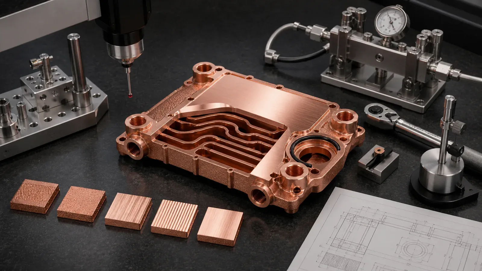
Figure 3. Illustrative inspection arrangement, not evidence of a passed test. A corrected design still needs an agreed route for finishing and verification.
Check What Each Design Correction Changes
A corrected CAD feature is not automatically a closed risk. Use this review worksheet to ask whether fixing one issue has created another. These are conditional design checks, not tested outcomes or instructions to make a particular geometry safe.
| Proposed correction | Possible new problem | Recheck before approving the change |
|---|---|---|
| Enlarge or straighten a channel | Less wall near a port or thermal face; changed flow distribution | Finished-state sections, remaining wall, thermal/hydraulic behavior, and acceptance plan |
| Add a powder-removal opening | A new closure, seal, or inaccessible cleaning interface | Closure route, assembly access, cleanliness, and leak-test boundary |
| Add stock or change a machining datum | Final channel-to-face distance or port relationship changes | Printed blank versus finished geometry, tool access, and drawing control |
| Increase a port boss | Fitting, wrench, or surrounding assembly loses clearance | Full thread/seat geometry, installation access, and interface loads |
| Change alloy or heat treatment | Earlier conductivity, strength, distortion, or compatibility assumptions no longer apply | Properties in the proposed final state and the evidence to repeat |
For example, enlarging a passage to aid cleaning can reduce the wall next to a threaded port. Do not close the cleaning action from a CAD screenshot and overlook the finished thread envelope. Keep both questions open until the geometry and verification route are agreed. If the constraints cannot be met together, reopen the channel layout, port location, or manufacturing route instead of accepting the local fix.
Record the affected feature, proposed change, coupled requirements, evidence needed, and approver. Carry only approved changes into the manufacturing revision. The CAD preparation guide covers file authority; the pre-quotation screening guide covers whether to proceed, condition, revise, or redirect the route.
Design Mistake Checklist Before RFQ
Use this checklist before sending a copper AM project for quotation.
| Review question | Risk if ignored | Better RFQ action |
|---|---|---|
| Why is this part printed? | AM replaces CNC without functional gain | State the geometry, channel, consolidation, or iteration reason |
| Are channels cleanable? | Powder remains trapped | Show section views, access openings, longest path, and flow direction |
| Are ports strong enough? | Thread damage, leak, torque failure | Define thread, boss thickness, pressure, seal method, and assembly load |
| Is machining stock included? | Functional faces cannot be finished | Separate printed blank from final machined state |
| Are tolerances zoned? | Quote becomes over-machined | Tighten only critical faces and datums |
| Is material open or fixed? | Wrong balance of conductivity and strength | State pure Cu, CuCrZr, CuCr1Zr, or function-first review |
| Is orientation over-constrained? | Support scars or cleaning problems | State functional surface restrictions, not arbitrary orientation |
| Is acceptance defined? | Part is printed but not provable | Add pressure, flow, CMM, CT, conductivity, hardness, or thermal test as needed |
If several rows are still unknown, the project can still start. It should start as a design-for-manufacturing review, not as a fixed production quote.
What to Send Instead of a Risky Design
For a better first review, send:
- STEP or Parasolid model.
- Native CAD file if design changes are allowed.
- 2D drawing with critical dimensions and surface notes.
- Section views for internal channels.
- Minimum wall thickness near ports and channels.
- Printed blank versus finished part explanation.
- Machining stock on functional surfaces.
- Material preference or openness.
- Quantity and development stage.
- Working pressure, proof pressure, flow, heat load, current, RF band, or service requirement.
- Inspection and acceptance expectations.
Use the short first-inquiry brief if requirements are still open. Send the known information through the online RFQ form or directly to info@szcomo.com, and identify the design questions rather than inventing missing values. An initial inquiry does not require a completed production specification.
FAQ
What is the most common design mistake in 3D printed copper parts?
The recurring issue addressed in this guide is designing the printed shape without defining the finished route. Missing machining stock, inaccessible channels, unsupported port requirements, undefined material state, and absent acceptance criteria each require review. Their priority depends on the actual part; this is not a frequency ranking from customer projects.
Can copper 3D printing make very small internal channels?
Sometimes, but small does not mean practical. Channel size must be reviewed with build orientation, powder removal, flushing, pressure drop, wall thickness, and inspection. A slightly larger cleanable channel can be better than a smaller channel that cannot be verified.
Should all copper AM surfaces be tightly toleranced?
No. Tight tolerances should be assigned to functional faces, datums, sealing lands, ports, contact pads, and critical interfaces. Nonfunctional areas can often remain as-built or receive lighter finishing. Blanket tolerance notes raise cost and ambiguity.
Is pure copper always the best choice for 3D printed copper parts?
No. Pure copper can be preferred for maximum thermal or electrical conductivity, but CuCrZr or CuCr1Zr may be better when strength, threaded ports, pressure boundaries, clamp load, or heat treatment matter. Material should be selected around the finished component.
How can we reduce design risk before requesting a quote?
Send CAD, drawing, section views, material preference, quantity, critical surfaces, operating conditions, and acceptance tests. If the design is still open, state that supplier DFM review is expected before locking the model.
Verdict: Design the Finished Copper Part, Not Just the Printed Shape
The biggest design mistakes in 3D printed copper parts are not exotic. They are practical: channels that cannot be cleaned, ports that cannot survive finishing, faces that need machining but have no stock, tolerances applied without function, material choices made from one property, and acceptance tests left until after the part is built.
Copper AM is strongest when it solves a real geometry problem: compact channels, integrated manifolds, shorter thermal paths, fewer joints, RF or vacuum consolidation, or combined cooling and conductivity. It is weakest when the design uses additive freedom without additive discipline.
Before locking the model, ask whether the part can be printed, depowdered, machined, cleaned, inspected, and accepted. If the answer is visible in the CAD package and RFQ notes, the design is ready for a serious quote. If the answer is hidden, the next step is not production. It is design review.
Related reading: Design Rules for Copper Laser Powder Bed Fusion Parts, How to Prepare CAD Files for Copper Metal 3D Printing, Cost Drivers in Copper 3D Printing Projects, When Copper 3D Printing Is Better Than CNC Machining, Copper AM Cleaning and Powder Removal for Internal Channels, and When a Copper Part Should Be Rejected for LPBF Before Quotation.
Copper AM quotation
Is copper AM a fit for your part?
Describe the part, its job, and the question holding up your decision. Add quantity and critical requirements if known; CAD can follow.
NDA available on request. We reply within 2 business days.
Before you submit: Copper AM capabilities and review scope.
